Supercharge Your Innovation With Domain-Expert AI Agents!

Micro-electromechanical fluid ejection device with control logic circuttry

a micro-electromechanical and logic circuit technology, applied in the direction of printing mechanism, power drive mechanism, printing, etc., can solve the problems of power consumption, low power consumption, and inability to meet the requirements of application

Inactive Publication Date: 2004-06-17
MEMJET TECH LTD +1
View PDF12 Cites 3 Cited by
  • Summary
  • Abstract
  • Description
  • Claims
  • Application Information

AI Technical Summary

Benefits of technology

The solution enhances the precision and reliability of ink ejection, improving print quality by ensuring consistent thermal expansion and contraction of the actuator arm, thereby stabilizing the ink ejection process and reducing variations in nozzle rim formation.

Problems solved by technology

This is because the two main contenders--thermal ink jet and piezoelectric ink jet--each have severe fundamental problems meeting the requirements of the application.
The most significant problem with thermal ink jet is power consumption.
This is approximately 100 times that required for these applications, and stems from the energy-inefficient means of drop ejection.
The high power consumption limits the nozzle packing density, as
The most significant problem with piezoelectric ink jet is size and cost Piezoelectric crystals have a very small deflection at reasonable drive voltages, and therefore require a large area for each nozzle.
This is not a significant problem at the current limit of around 300 nozzles per print head, but is a major impediment to the fabrication of page width print heads with 19,200 nozzles.

Method used


Image

  • Micro-electromechanical fluid ejection device with control logic circuttry
  • Micro-electromechanical fluid ejection device with control logic circuttry
  • Micro-electromechanical fluid ejection device with control logic circuttry

Examples


Embodiment Construction

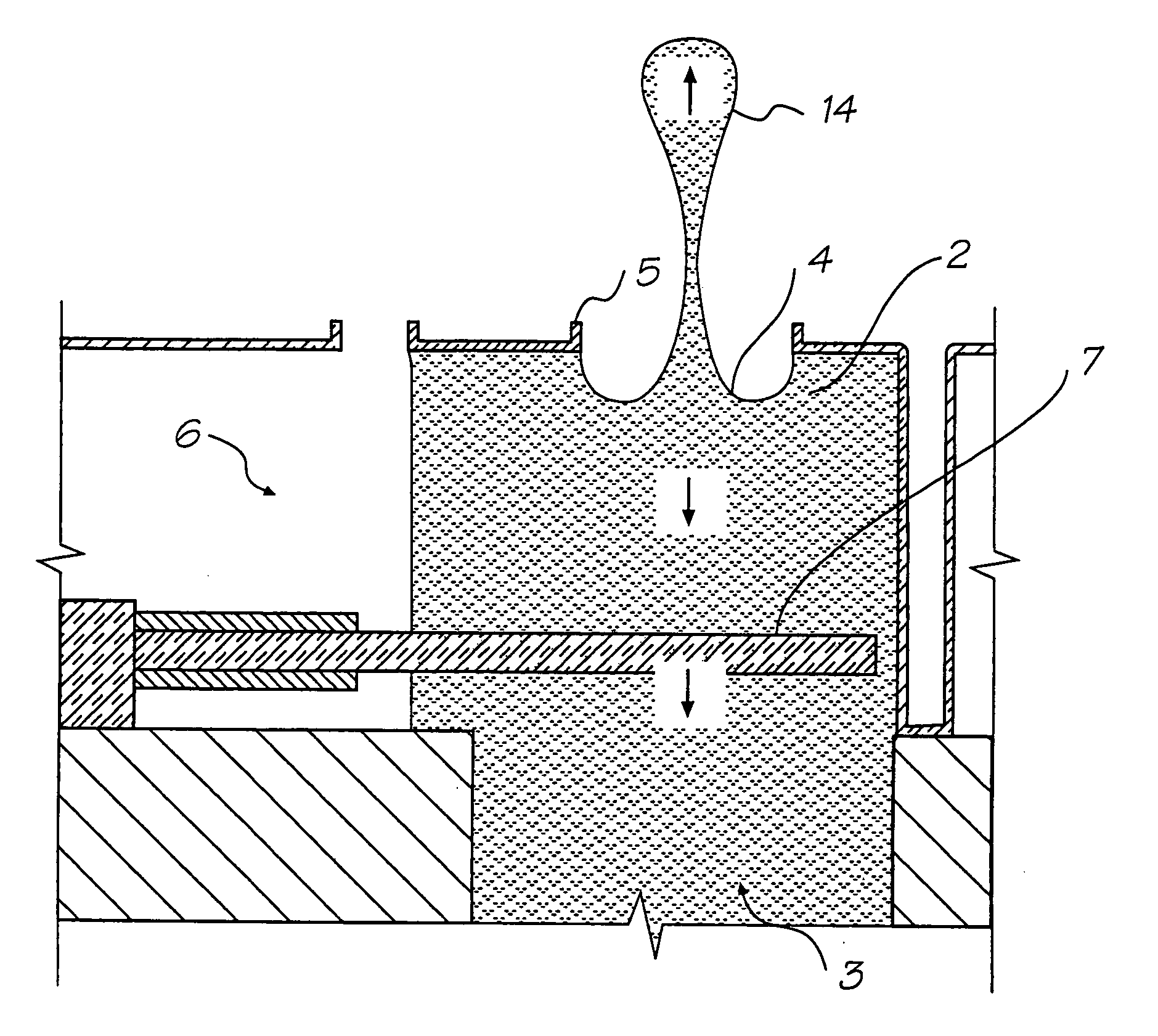
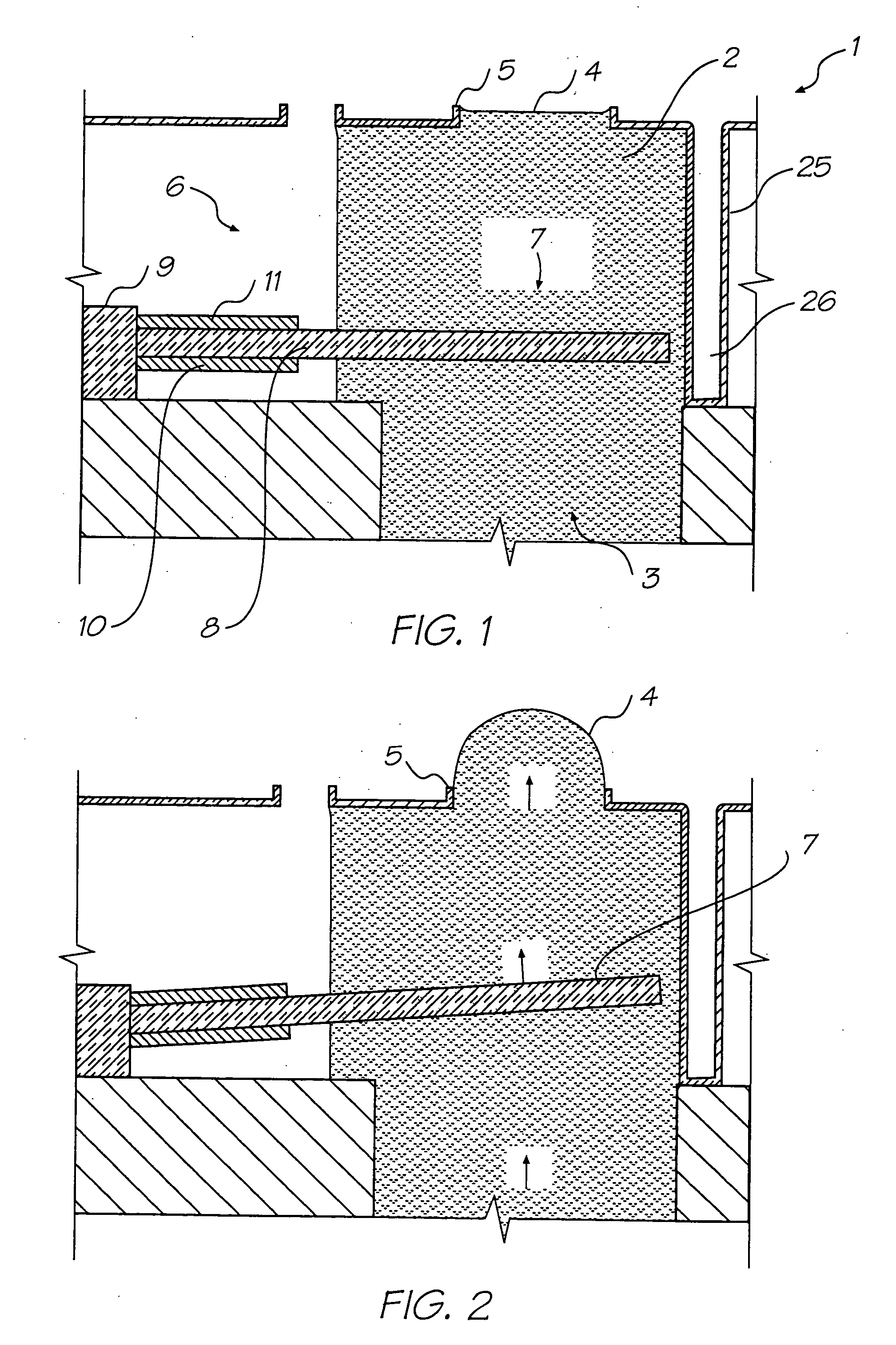
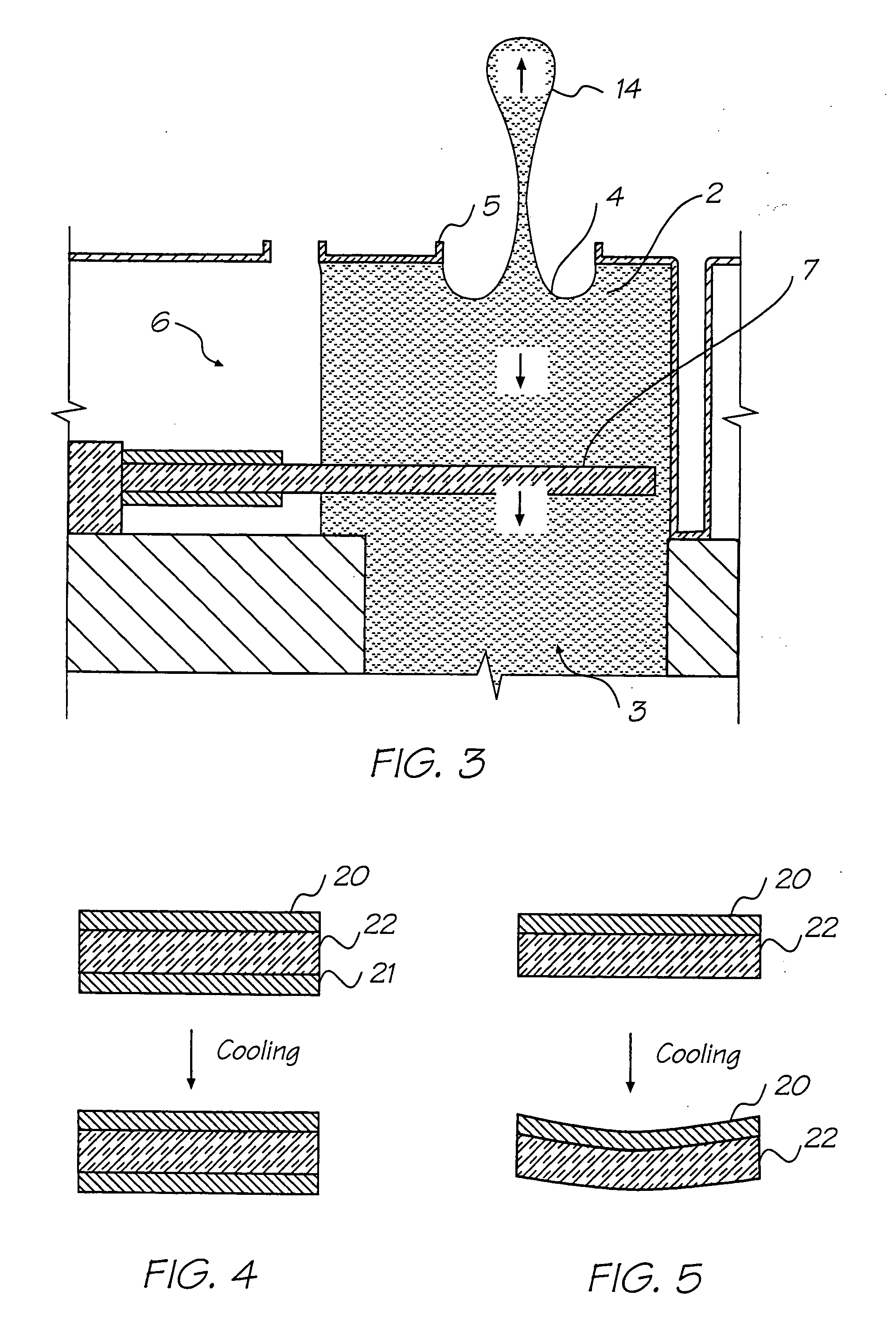
[0228] The preferred embodiment is a 1600 dpi modular monolithic print head suitable for incorporation into a wide variety of page width printers and in print-on-demand camera systems. The print head is fabricated by means of Micro-Electro-Mechanical-Systems (MEMS) technology, which refers to mechanical systems built on the micron scale, usually using technologies developed for integrated circuit fabrication.

[0229] As more than 50,000 nozzles are required for a 1600 dpi A4 photographic quality page width printer, integration of the drive electronics on the same chip as the print head is essential to achieve low cost. Integration allows the number of external connections to the print head to be reduced from around 50,000 to around 100. To provide the drive electronics, the preferred embodiment integrates CMOS logic and drive transistors on the same wafer as the MEMS nozzles. MEMS has several major advantages over other manufacturing techniques:

[0230] mechanical devices can be built w...


PUM


Abstract

A micro-electromechanical fluid ejection device includes a substrate. A nozzle chamber wall and a roof wall are positioned on the substrate to define a nozzle chamber and an ink ejection port in the roof wall. An elongate actuator arm has a fixed end portion is fast with the substrate and a free end portion that is spaced from the substrate. The elongate actuator arm incorporates a heating circuit that is connectable to a power supply to heat the actuator arm. The heating circuit is positioned to generate differential thermal expansion and contraction when heated and subsequently cooled to cause reciprocal displacement of the free end portion of the actuator arm. A fluid ejection member is fast with the free end of the elongate actuator arm to be positioned in the nozzle chamber such that said displacement of the free end portion of the actuator arm results in the ejection of fluid from the ink ejection port. Control logic circuitry is positioned on the substrate along an elongate region defined on the substrate and interposed between the actuator arm and the substrate. The control logic circuitry is connected to the heating circuit to enable and disable the power supply according to a control signal received by the control logic circuitry.

Description

[0001] This is a Continuation application of U.S. Ser. No. 09 / 835,702 filed on Apr. 16, 2001[0002] The present invention relates to the construction of micro-electro mechanical devices such as ink jet printers.[0003] In international patent application PCT / AU98 / 00550, the present applicant has proposed an ink jet printing device which utilizes micro-electro mechanical (MEMS) processing techniques in the construction of a print head driven by thermal bend actuator devices for the ejection of fluid such as ink from an array of nozzle chambers.[0004] Devices of this type have a number of limitations and problems.[0005] It is an object of the present invention to provide various aspects of an inkjet printing device which overcomes or at least ameliorates one of or more of the disadvantages of the prior art or which at least offers a useful alternative thereto.[0006] According to a first aspect of the invention, there is provided a micro-electromechanical fluid ejection device that compr...

Claims


Application Information

Patent Timeline
Patent Type & Authority Applications(United States)
IPC IPC(8): B41J2/05B41J2/14B41J2/16
CPCB41J2/04505B41J2002/14491B41J2/04518B41J2/0452B41J2/04528B41J2/04541B41J2/04543B41J2/04553B41J2/04563B41J2/04565B41J2/0457B41J2/04571B41J2/04585B41J2/04588B41J2/0459B41J2/04591B41J2/04593B41J2/04596B41J2/04598B41J2/14427B41J2/155B41J2/1601B41J2/1623B41J2/1628B41J2/1629B41J2/1631B41J2/1632B41J2/1635B41J2/1637B41J2/1639B41J2/1642B41J2/1646B41J2/1648B41J25/005B41J2002/14419B41J2/04516
Inventor SILVERBROOK, KIA
Owner MEMJET TECH LTD
Features
  • R&D
  • Intellectual Property
  • Life Sciences
  • Materials
  • Tech Scout
  • Unparalleled Data Quality
  • Higher Quality Content
  • 60% Fewer Hallucinations
Learn More