Determining method of high pressure of refrigeration cycle apparatus

a technology of high pressure and refrigeration cycle, which is applied in the direction of domestic cooling apparatus, lighting and heating apparatus, refrigeration components, etc., can solve the problems of difficult to maintain optimal cop and deterioration of the operation efficiency of the refrigeration cycle apparatus compared with a conventional refrigeran

Inactive Publication Date: 2004-06-24
PANASONIC CORP
View PDF7 Cites 25 Cited by
  • Summary
  • Abstract
  • Description
  • Claims
  • Application Information

AI Technical Summary

Problems solved by technology

When a temperature higher than this temperature is utilized, a high pressure side (outlet of the compressor-gas cooler-inlet of pressure reducing device) of the refrigeration cycle apparatus is brought into a supercritical state in which CO.sub.2 refrigerant is not condensed, and there is a feature that operation efficiency of the refrigeration cycle apparatus is deteriorated as compared with a conventional refrigerant.
However, when the refrigeration

Method used


Image

  • Determining method of high pressure of refrigeration cycle apparatus
  • Determining method of high pressure of refrigeration cycle apparatus
  • Determining method of high pressure of refrigeration cycle apparatus

Examples


Embodiment Construction

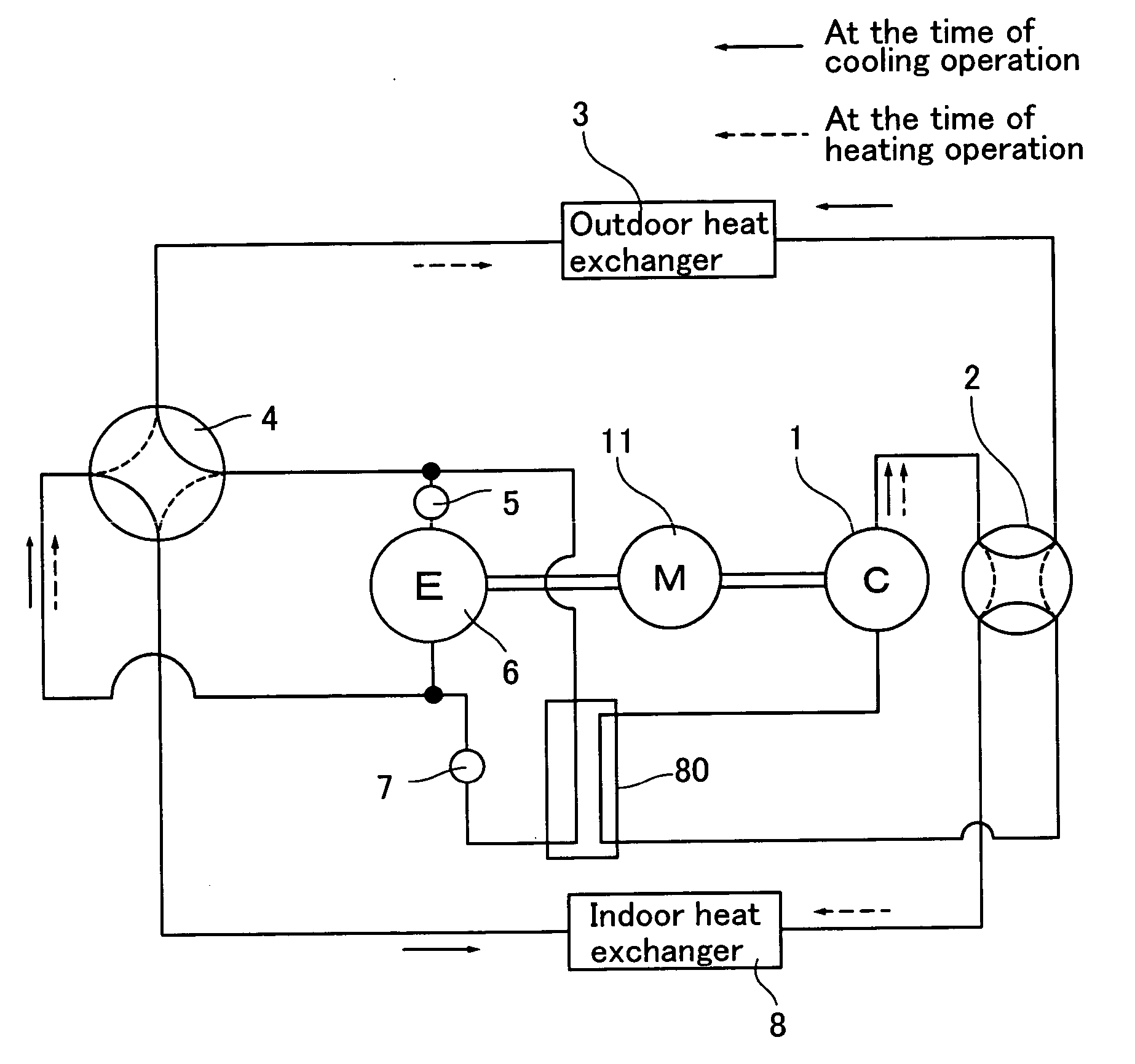
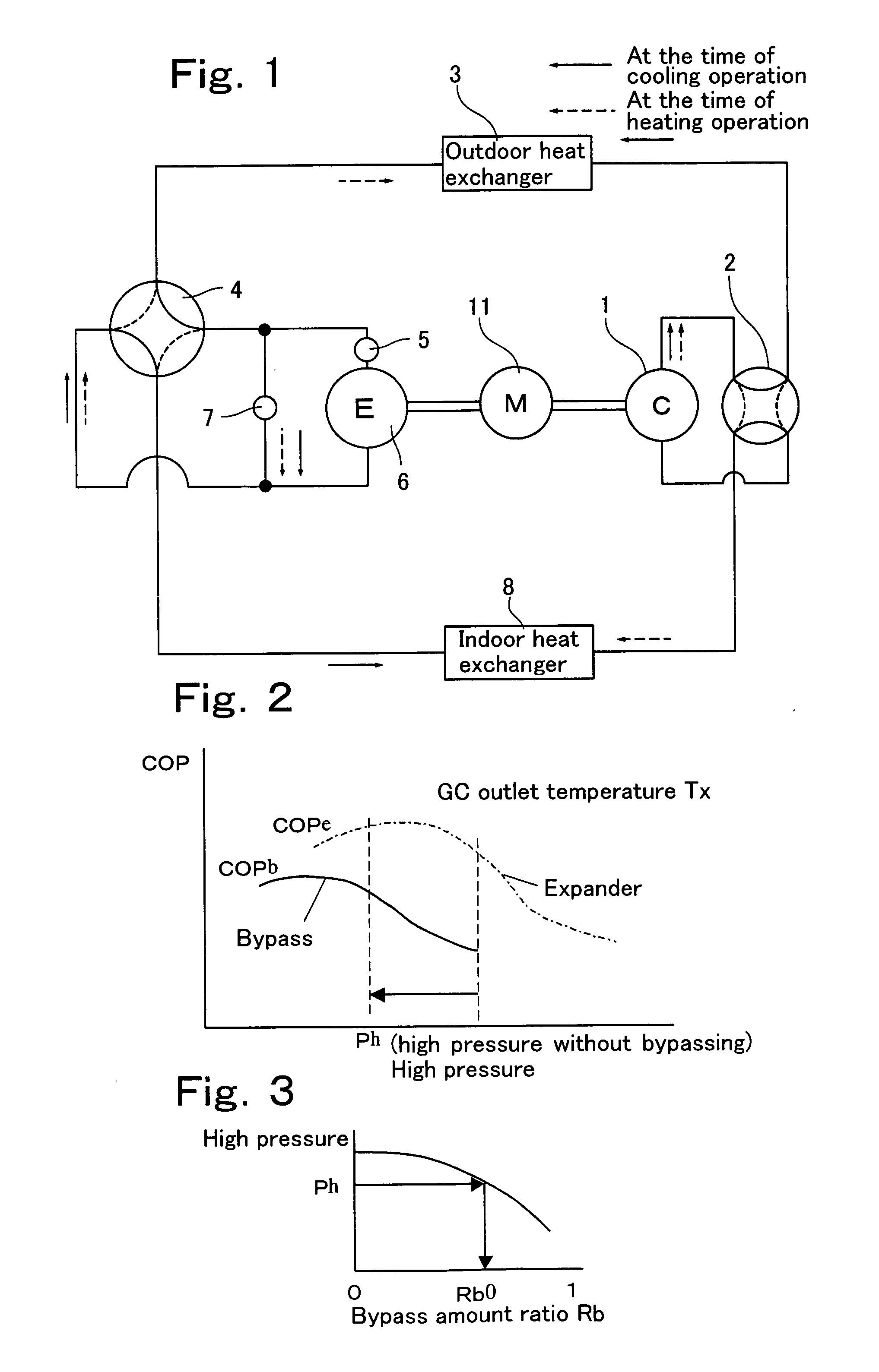
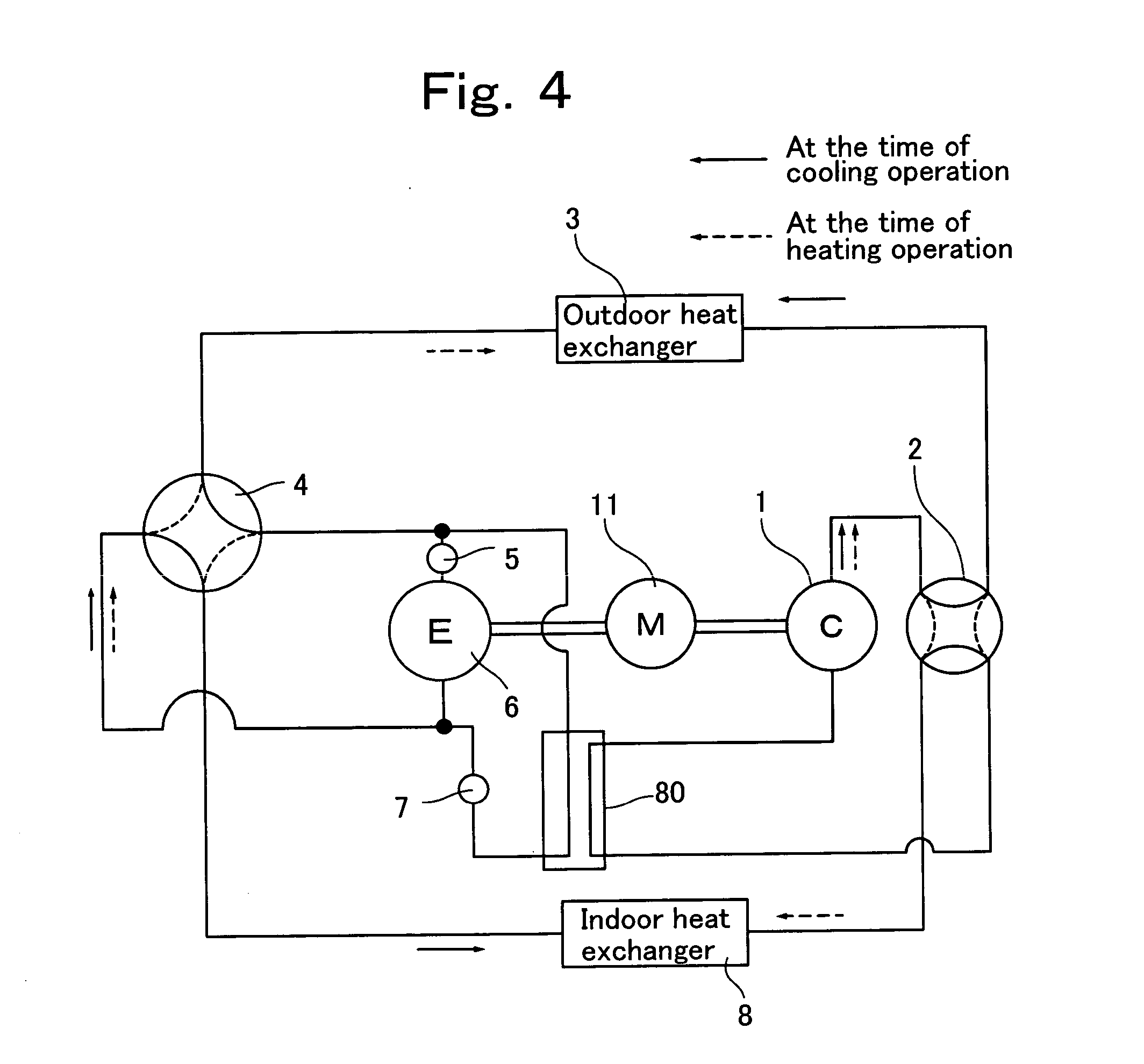
[0034] A refrigeration cycle apparatus according to an embodiment of the present invention will be explained with reference to the drawing below based on a heat pump type cooling and heating air conditioner.

[0035] FIG. 1 shows a structure of the heat pump type cooling and heating air conditioner of the present embodiment.

[0036] As shown in FIG. 1, the heat pump type cooling and heating air conditioner of this embodiment uses CO.sub.2 refrigerant as refrigerant, and has a refrigerant circuit. The refrigerant circuit comprises a compressor 1 having a motor 11, an outdoor heat exchanger 3, an expander 6, and an indoor heat exchanger 8 which are all connected to one another through pipes.

[0037] The expander 6 is provided at its inflow side with a pre-expansion valve 5.

[0038] A bypass circuit which bypasses the pre-expansion valve 5 and the expander 6 is provided in parallel to the pre-expansion valve 5 and the expander 6. The bypass circuit is provided with a control valve 7.

[0039] A dr...


PUM


Abstract

It is an object of the present invention to reduce the constraint that the density ratio is constant as small as possible, and to obtain high power recovering effect in a wide operation range by using an expander which is operated in accordance with a flowing direction of refrigerant. A determining method of a high pressure of a refrigeration cycle apparatus in which a refrigeration cycle uses carbon dioxide as refrigerant and has a compressor, an outdoor heat exchanger, an expander and an indoor heat exchanger, and the refrigeration cycle including a bypass circuit provided in parallel to said expander, and a control valve which adjusts a flow rate of refrigerant flowing through said bypass circuit, said compressor being driven by power recover by said expander, wherein if an optimal high pressure of a first refrigeration cycle flowing through said expander and a second refrigeration cycle flowing through said bypass circuit is defined as Ph, and a bypass amount ratio flowing through said bypass circuit in said Ph is defined as Rb0, and a maximum refrigeration cycle efficiency of said first refrigeration cycle in said Ph is defined as COPe, and a maximum refrigeration cycle efficiency of said second refrigeration cycle in said Ph is defined as COPb, the optimal high pressure Ph which maximizes (1-Rb0)xCOPe+Rb0xCOPb is determined.

Description

[0001] The present invention relates to a refrigeration cycle apparatus in which a refrigeration cycle uses carbon dioxide as refrigerant and has a compressor, an outdoor heat exchanger, an expander and an indoor heat exchanger, and the refrigeration cycle including a bypass circuit provided in parallel to the expander, and a control valve which adjusts a flow rate of refrigerant flowing through the bypass circuit, the compressor is driven by power recover by the expander.BACKGROUND TECHNIQUE[0002] A flow rate of refrigerant which circulates through a refrigeration cycle apparatus is all the same in any points in a refrigeration cycle. In a cycle in which a compressor and an expander coaxially rotate, if a suction density of refrigerant passing through a compressor is defined as DC and a suction density of refrigerant passing through an expander is defined as DE, the DE / DC (density ratio) is always constant.[0003] In recent years, attention is focused on a refrigeration cycle appara...

Claims


Application Information

Patent Timeline
IPC IPC(8): F25B9/00F25B9/06F25B11/02F25B13/00F25B1/00F25B40/00
CPCF25B9/008F25B9/06F25B13/00F25B2600/2501F25B2309/061F25B2400/04F25B2600/17F25B40/00
Inventor NAKATANI, KAZUOKAWABE, YOSHIKAZUOKAZA, NORIHOINOUE, YUJIHIWATA, AKIRA
Owner PANASONIC CORP
Why Eureka
Try Eureka