
Allocation of optical fibers for parameter managed cables and cable systems

a technology of parameter management and optical fibers, applied in the direction of optical waveguide light guide, electromagnetic network arrangement, instruments, etc., can solve the problems of tighter or narrower psys-max or psys, high-performance transmission system problems, and the inability to achieve normalized specification values so restrictively

Inactive Publication Date: 2004-06-24
CORNING CABLE SYST LLC
View PDF7 Cites 2 Cited by
  • Summary
  • Abstract
  • Description
  • Claims
  • Application Information

AI Technical Summary

Benefits of technology

The present invention relates to fiber optic cables and systems used for high-speed data transmission. The invention addresses the issue of reliable signal transmission performance in high-rate optical transmission systems, which can be affected by various parameters such as length-dependent characteristics, polarization mode dispersion, chromatic dispersion, and modal dispersion. The invention provides a method for managing these parameters to ensure reliable performance of the optical transmission system. The traditional methods for selecting fibers for the system are static and cannot dynamically account for changes in the characteristics of the fibers, which can result in a limited system length. The statistical method described in the invention takes into account the use of system components such as optical amplifiers and dispersion compensators, and can dynamically account for changes in the characteristics of the fibers.

Problems solved by technology

Since optical fiber symmetry is not perfect, and forces acting on the fiber are not uniformly applied, polarization modes may experience conditions that affect their propagation, whereby the modes will travel at different speeds.
PMD can cause problems in high performance transmission systems.
A problem exists, however, for longer systems with tighter or narrower Psys-max or Psys.+-.range values.
The normalized specification value can become so restrictive that manufacturing cables acceptable for the system becomes increasingly more difficult.
The foregoing statistical method can be difficult to manage, however.
The maximum system length that can be reached using either of the foregoing methods is limited.
In addition, the foregoing methods do not take into account the use of optical transmission system components, for example, optical amplifiers and dispersion compensators.
Additionally, the traditional methods are essentially static, and cannot dynamically account for installed cable lengths as the cable build progresses, nor can it account for multiple linear dependent parameters.

Method used

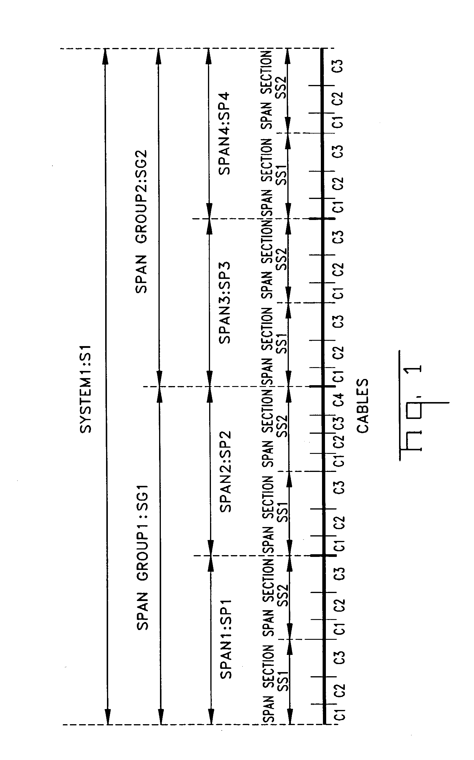
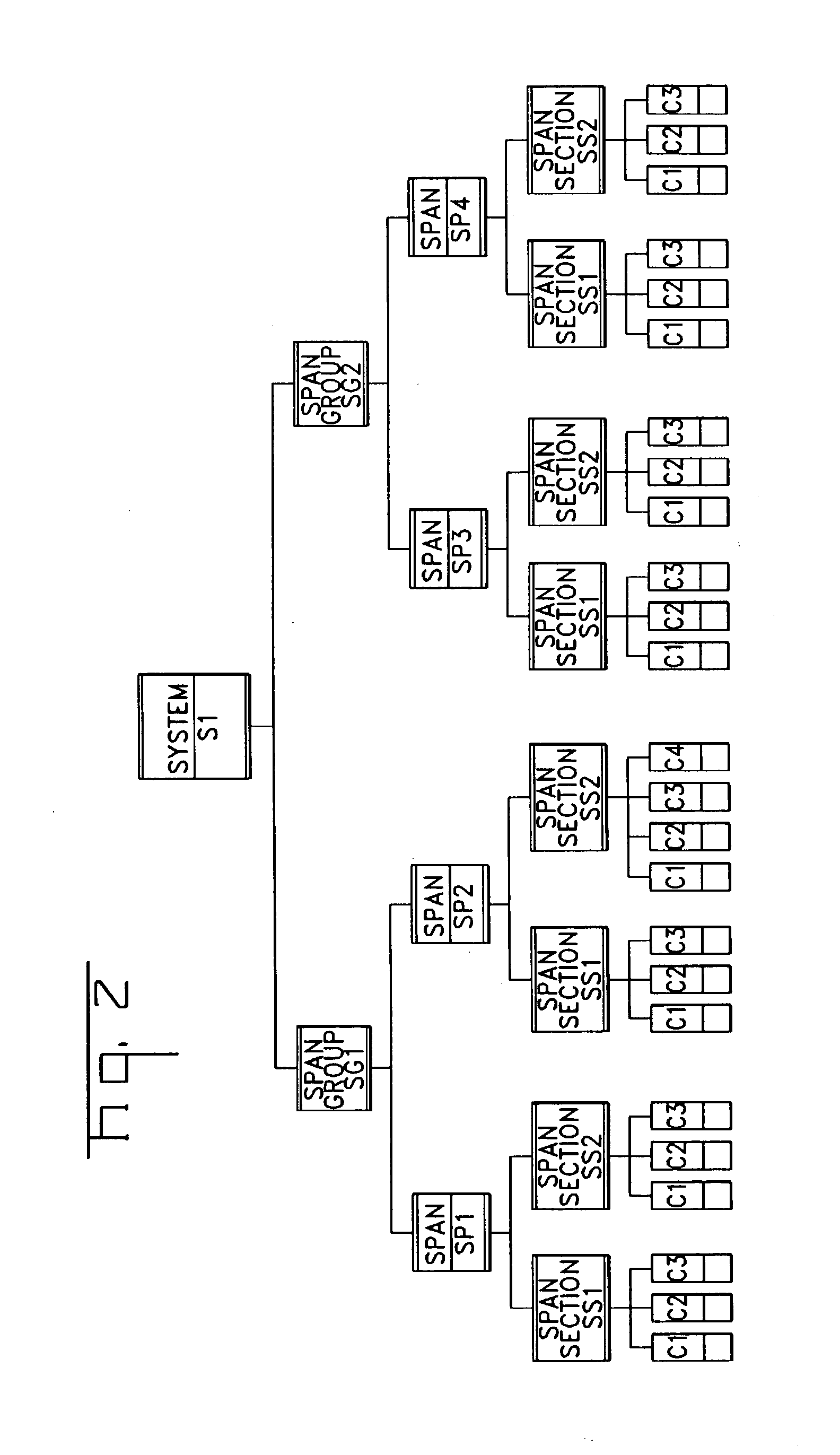
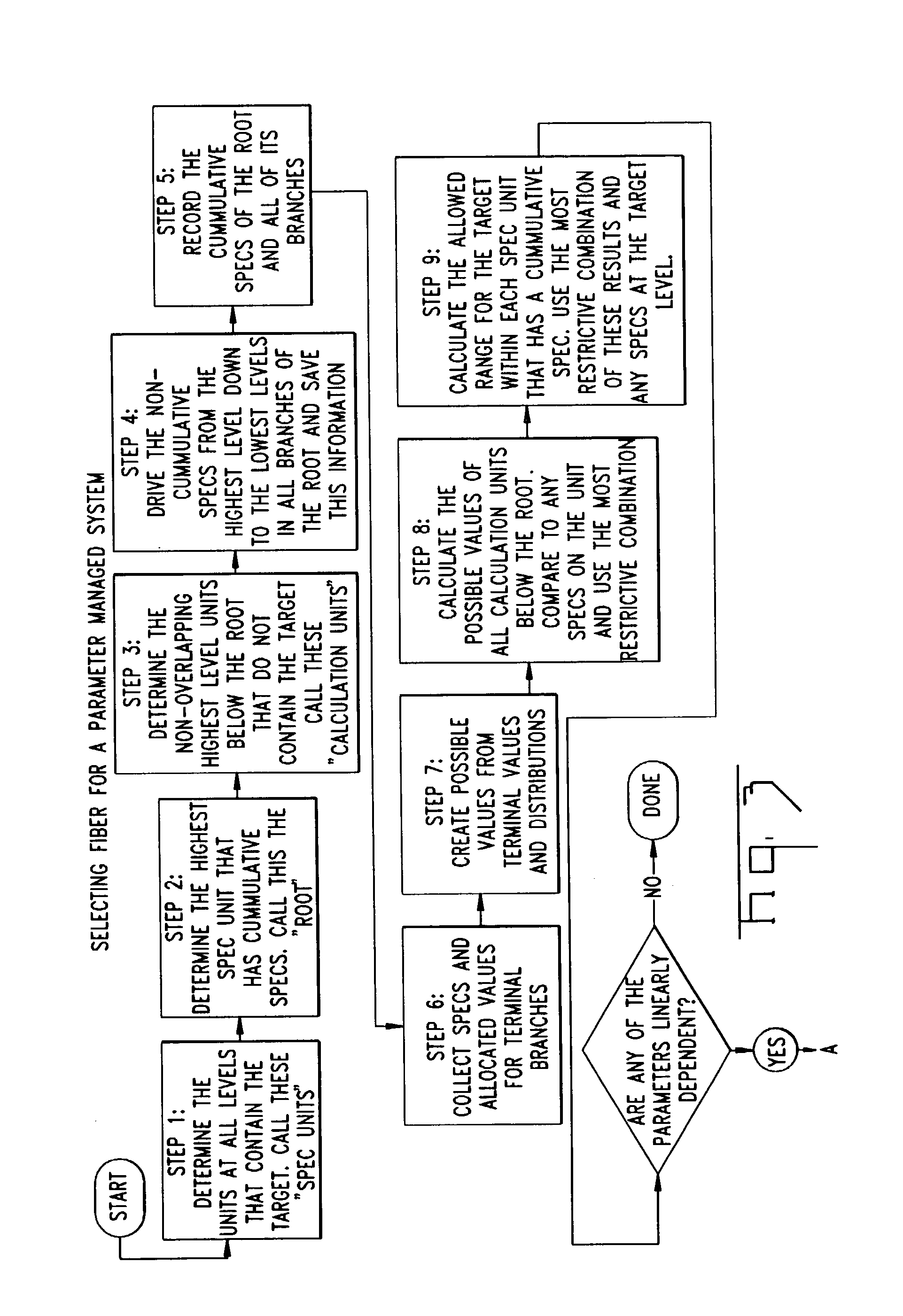

Image

  • Allocation of optical fibers for parameter managed cables and cable systems
  • Allocation of optical fibers for parameter managed cables and cable systems
  • Allocation of optical fibers for parameter managed cables and cable systems

Examples


example

[0109]

12 Per / km per fiber DISP@1560 40 320 DISP@1620 47 376 ATTEN@1550 0.2 1.6

[0110] Step 11:

[0111] Determine the allowable range for unallocated fiber that will keep each spec unit within its specs for 1560 nm dispersion.

[0112] Calculate these base ranges, example:

13 Min Max Min Max Total unallocated unallocated Total Min Max Spec Unit spec spec allocated @1560 @1560 allocated spec spec ID Level @1560 @1560 @1560 U.sub.min1 U.sub.max1 @1620 @1620 @1620 S1 1 None None S1-SG1 2 -20 20 416 -756 -716 432 -20 20 S1-SG1-SP1 3 -30 30 416 -766 -706 432 -30 30 S1-SG1-SP1- 4 None None SS1

[0113] Steps 12-15:

[0114] Convert each base range into the corresponding values for each essentially linearly dependent parameter using equations 11 and 12 excluding the first parameter. Then for each dependant parameter (excluding the first) take the most restrictive overlap of the converted ranges, and use the most restrictive range for each dependant parameter (excluding the first) to calculate the range ...


PUM


Abstract

An optical path for voice, video, and data transmission, and methods for manufacturing optical cables for use in optical transmission systems. The optical path or sub-paths have linearly and or non-linearly length dependant parameters which may have mutual relationships, for which local selection criteria allows a minimally restrictive local selection.

Description

[0001] The present invention relates to the field of fiber optic cables, and, more particularly, to fiber optic cables having optical fibers with optical characteristics managed for reliable signal transmission performance in high data rate optical transmission systems.GENERAL BACKGROUND OF THE INVENTIONS[0002] Fiber optic cables and systems are used to transmit telephone, television, and computer data information in indoor and outdoor environments. Optical performance can be affected by length dependent parameters, for example, optical attenuation, polarization mode dispersion, chromatic dispersion, and / or modal dispersion. Attenuation is a measure of loss of optical power over a system or length of fiber that is typically measured in dB / km. Since optical fiber symmetry is not perfect, and forces acting on the fiber are not uniformly applied, polarization modes may experience conditions that affect their propagation, whereby the modes will travel at different speeds. This effect is...

Claims


Application Information

Patent Timeline
Patent Type & Authority Applications(United States)
IPC IPC(8): G02B6/34
CPCH04B10/27G02B6/29376
Inventor GALLAGHER, BRIAN F.RAYMOND, MICHAEL R.WITZEL, DONALD M.FEDOROFF, MICHAEL S.JACKMAN, WILLIAM S.YOUNG, FERN E.KNUTTILA, HOLLY
Owner CORNING CABLE SYST LLC
Learn More