Engine pylon suspension attachment of an engine under an aircraft wing section

a technology of aircraft wings and suspension attachments, which is applied in the direction of machine supports, other domestic articles, transportation and packaging, etc., can solve the problems of affecting the implantation of engines of larger diameters, affecting the insertion of engines, and having significant bulkiness in vertical directions, so as to reduce the vertical space requirement of the strut, increase the distance between the joining elements, and increase the size of the fasteners

Inactive Publication Date: 2004-07-08
AIRBUS OPERATIONS (SAS)
View PDF13 Cites 26 Cited by
  • Summary
  • Abstract
  • Description
  • Claims
  • Application Information

AI Technical Summary

Benefits of technology

[0020] The object of the invention also is to propose an original strut whereof the hooking device implants on the existing plane a heavier engine and of greater diameter, by reducing to a minimum the modifications made to the wing body assembly of the plane.
[0022] In this arrangement, progressive widening of the strut in its rear part and mounting in the rear fastener of the joining elements, serving especially to recover a portion of the forces transmitted in the vertical direction as well as the moment along the longitudinal axis, effectively and substantially increasing the distance between said joining elements relative to the prior art. As a consequence, it becomes possible to transfer much more significant forces without substantially increasing the size of the fasteners. Heavier and more powerful engines can thus be installed under the wing body assembly of existing planes.
[0023] In addition, the vertical space requirement of the strut can be reduced, enabling installation of engines of greater diameter while acceptable ground clearance is maintained.
[0027] Relative to the preceding, this second embodiment of the invention effectively eliminates any recess in the lower wing surface covering of the wing body assembly. Therefore, the increase in the complexity and the cost of the wing body assembly, the problems of tightness of the fuel tank integrated into the wing body assembly and the decreases in capacity of this tank which flow from the presence of relief in the lower wing surface covering of the wing body assembly are eliminated.

Problems solved by technology

Nevertheless, it is a disadvantage to have significant bulkiness in a vertical direction, due to the fact of the presence of shackles connecting braces which protrude upwards above the strut and downwards under the wing body assembly.
This disadvantage can be prejudicial if the decision is made to equip an existing plane with more powerful engines, so as to increase its pay load at takeoff and / or to decrease its fuel consumption.
Considering the space requirement of existing struts in the vertical direction, especially at the level of the devices ensuring they are hooked ob beneath the wing body assembly, it seems that implantation of engines of larger diameter is very limited due to the decrease in ground clearance of the engines when the aircraft is landed.
Another problem concerns the increase in forces which must be transmitted to the wing body assembly via the strut, on account of the increased power and the size of the engines.
This would lead to an additional increase in the bulk of the plane, counteracting the desired aim.

Method used


Image

  • Engine pylon suspension attachment of an engine under an aircraft wing section
  • Engine pylon suspension attachment of an engine under an aircraft wing section
  • Engine pylon suspension attachment of an engine under an aircraft wing section

Examples


first embodiment

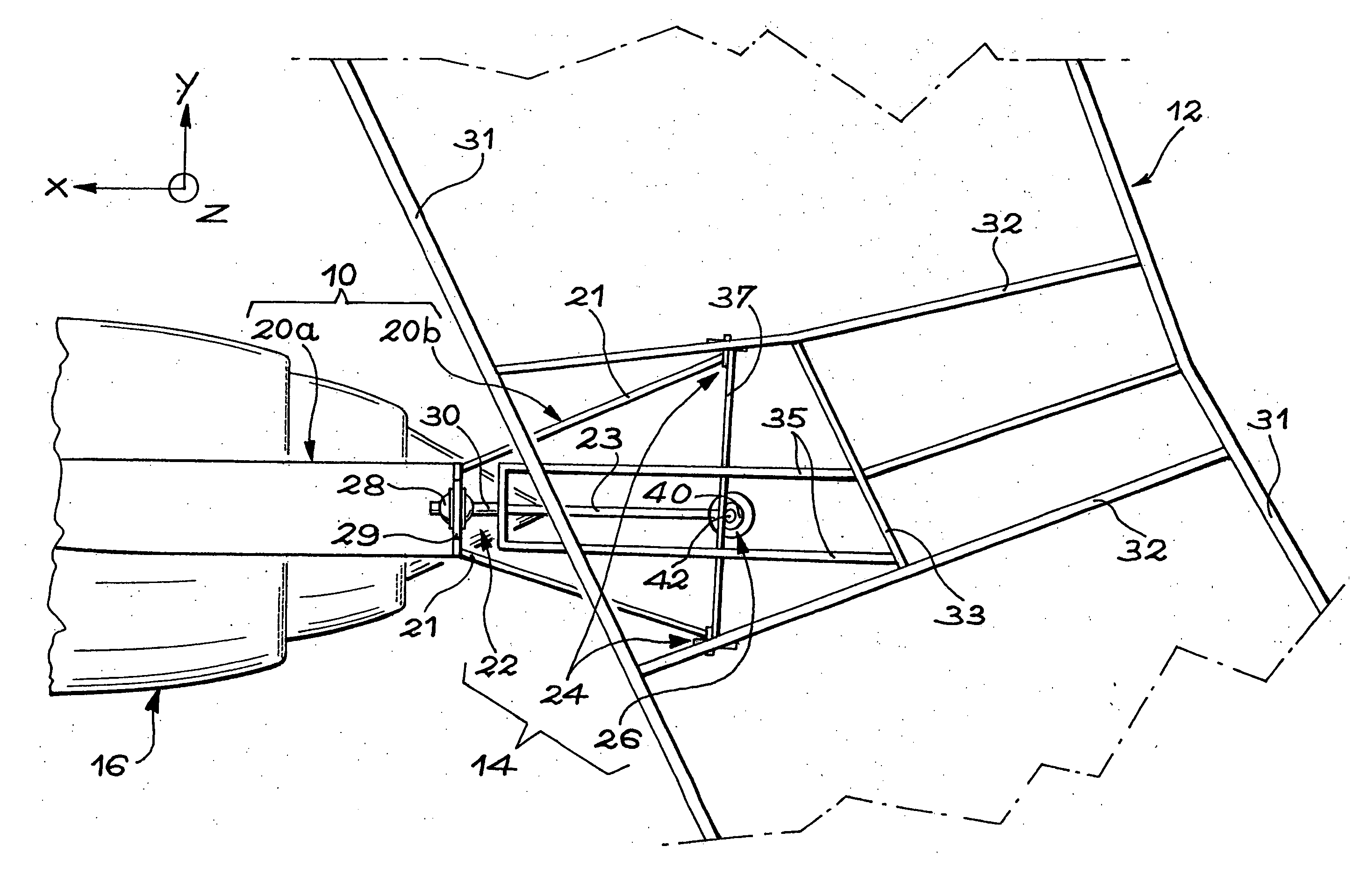
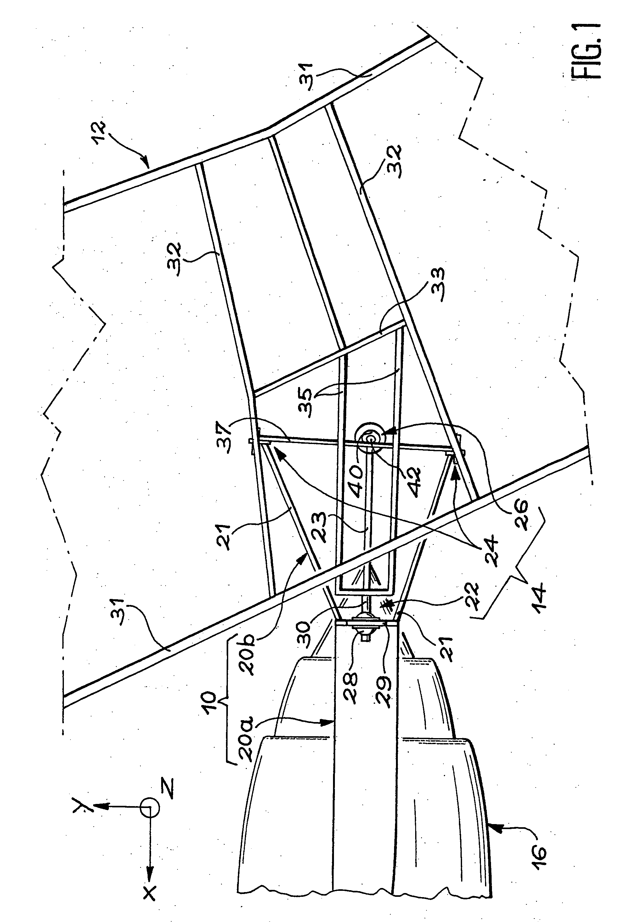
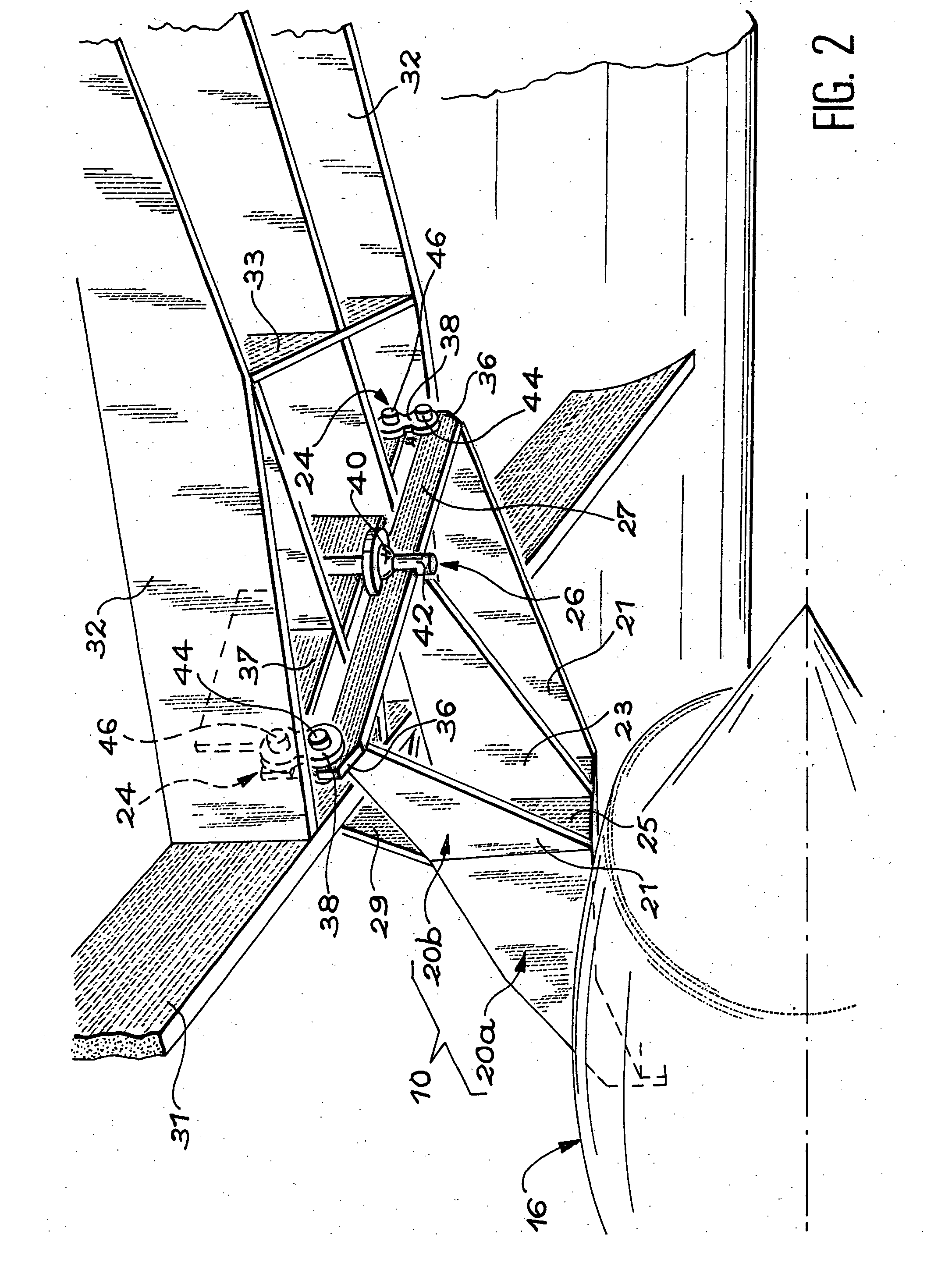
[0058] Further to the rear brace 36, each of the rear fasteners 24 comprises a joining element which connects each of the rear braces 36 to a structural part of the wing body assembly 12, constituted in this case by the intermediate transverse rib 37. this joining element will be described with reference to FIGS. 2 and 3.

[0059] In this first embodiment, the sealing element of each rear fastener 24 comprises a shackle 38, preferably double, which connects the brace 36 to the wing body assembly 12. More precisely, each of the shackles 38 is oriented substantially in the vertical direction Z and connects one of the rear braces 36 to the intermediate transverse rib 37, in the vicinity of the longitudinal ribs 32. The shackles 38 are located in the same plane YZ and are articulated respectively on the braces 36 and on the rib 37 by first hinge pins 44 and by the second hinge pins 46 oriented in the longitudinal direction X of the engine.

[0060] With the hinge pins 44 and 46 by which it is...

second embodiment

[0074] These drawbacks are eliminated in the invention which will be described with reference to FIG. 5.

[0075] In this second embodiment of the invention, the shackles are eliminated and each of the joining elements comprises a single hinge pin 48, a first piece 50 in the form of a disc and a second piece 52 in the form of a disc, generally identical to the first.

[0076] More precisely, the first piece 50 in the form of a disc is mounted in a cylindrical hole 56 passing through one of the rear braces 36 along a first axis A1 oriented in a longitudinal direction of the engine, such that the first piece 50 can turn freely about this first axis.

[0077] Comparably, the second piece 52 in the form of a disc is arranged in a cylindrical hole 58 which passes through a foot providing the support 54 along a second axis A2 oriented in a longitudinal direction of the engine, such that the second piece 52 can pivot freely about this second axis. More precisely, the foot providing the support 54 i...


PUM


Abstract

A strut (10) for hooking an engine (16) under a wing body assembly (12) of an aircraft comprises a rigid structure as well as a mechanism for hooking this structure under the wing body assembly. This mechanism comprises a front fastener (22), a rear fastener (24) and a structure (26) for absorbing thrust. To install an engine (16) of greater diameter under the wing body assembly (12) of an existing plane, the rear part (20b) of the strut (10) is given a width which increases as it progresses to the rear. Furthermore, the rear fastener (24) comprises two braces which are fixed on both sides of the rigid structure and two shackles which connect each of the braces to an additional transverse rib integrated into the wing body assembly.

Description

[0001] This application claims priority on International Patent Application No. PCT / FR03 / 00626 entitled "Hooking Strut of an Engine Under the Wing Unit of an Aircraft" by Herve MARCHE, which claims priority of French application no. 02 02698, filed on Mar. 4, 2002 and which was not published in English.DESCRIPTION[0002] 1. Technical Domain[0003] The invention relates to a strut for ensuring hooking or suspension of an engine under a wing body assembly of an aircraft. More precisely, the invention relates to a strut of structure original, as well as the device by which the strut is suspended on the wing body assembly.[0004] Such a device can be utilised on any type of aircraft comprising engines suspended under the wing body assembly by way of struts. It is particularly adapted to planes equipped with engines whose diameter is substantial relative to the space available under the wing body assembly when the plane is on the ground.[0005] 2. Prior Art[0006] In existing planes, the engi...

Claims


Application Information

Patent Timeline
Patent Type & Authority Applications(United States)
IPC IPC(8): B64D27/18B64D27/26
CPCB64D27/18Y02T50/44B64D2027/264B64D27/26Y02T50/40
Inventor MARCHE, HERVE
Owner AIRBUS OPERATIONS (SAS)
Why Eureka
Try Eureka