Power steering system

a technology of steering system and power steering, which is applied in the direction of fluid couplings, couplings, transportation and packaging, etc., can solve the problems of deteriorating steering feel and variable oil quantity of operation

Inactive Publication Date: 2004-07-15
HITACHI LTD
View PDF8 Cites 14 Cited by
  • Summary
  • Abstract
  • Description
  • Claims
  • Application Information

AI Technical Summary

Problems solved by technology

The above compensation may, however, cause variation in operation oil quantity between the first oil passage and the second oil passage.
A delay in the steering assistance may thus be caused, rapidly fluctuating torque of the steering wheel, resulting in deteriorated steering feel.

Method used


Image

  • Power steering system
  • Power steering system
  • Power steering system

Examples


first embodiment

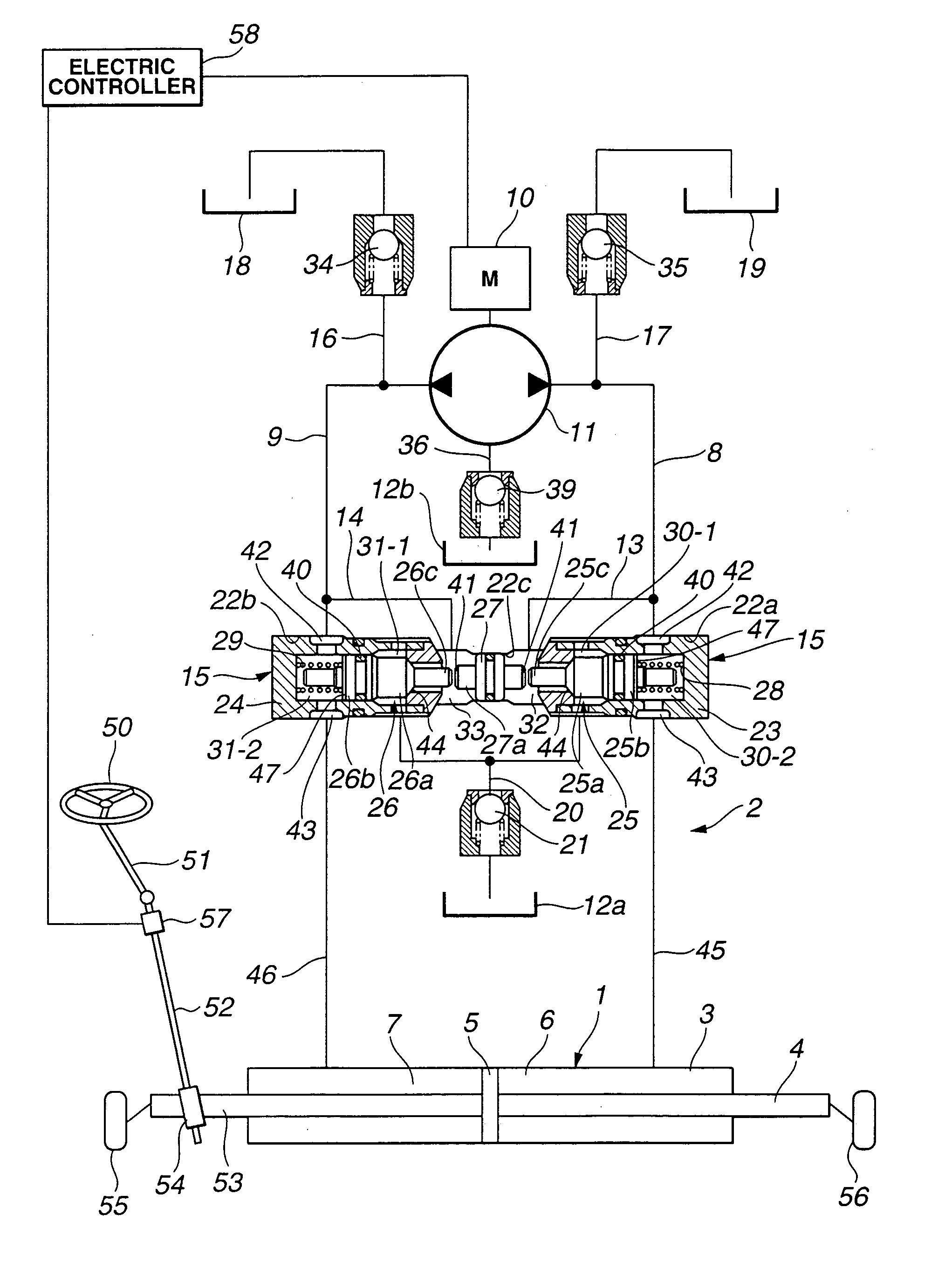
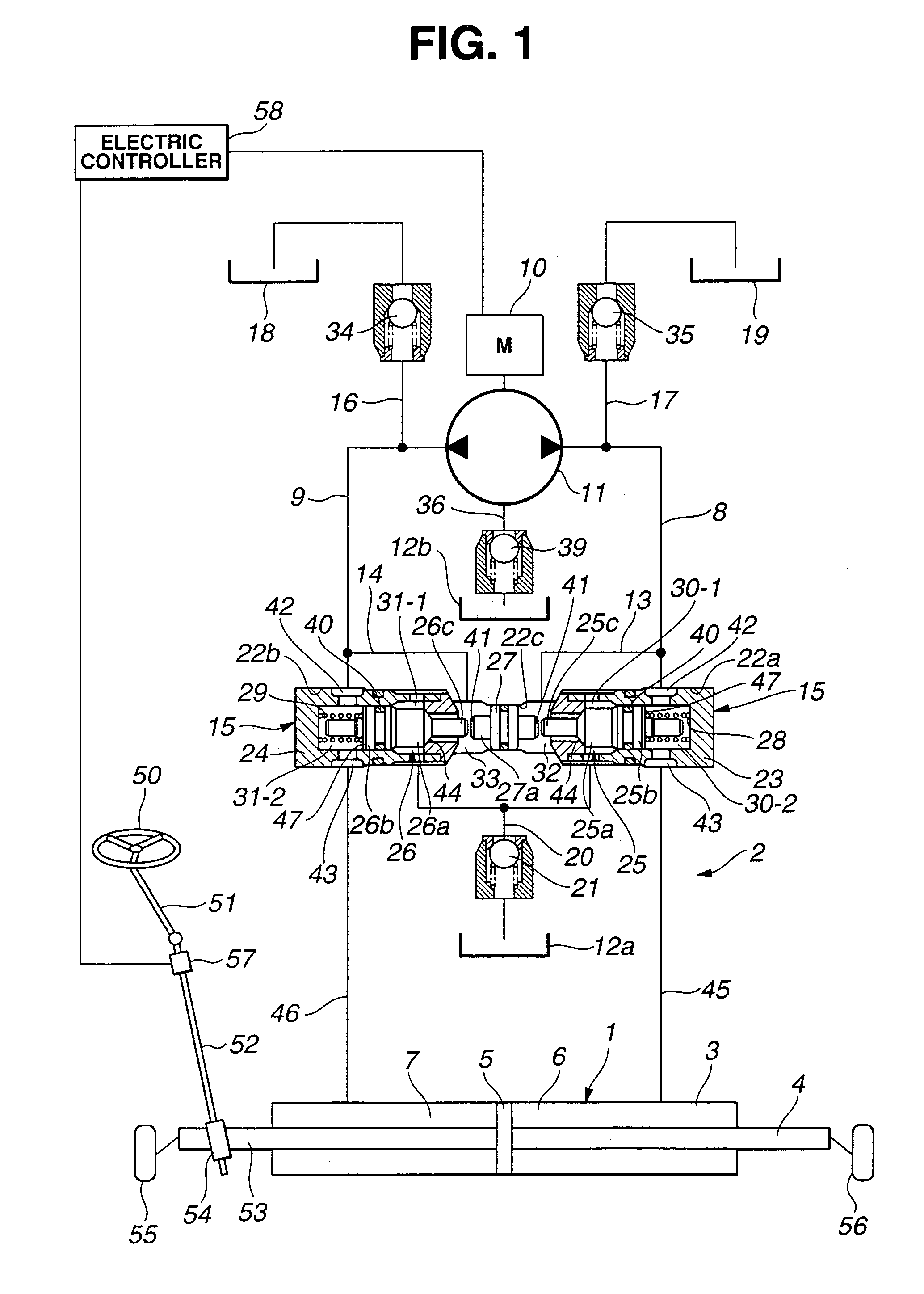
[0067] FIG. 1 shows principally an oil pressure cylinder 1 and an oil pressure circuit 2 of a power steering system, according to the present invention. Schematically, the power steering system has a steering wheel 50, an input shaft 51, an output shaft 52, a rack 53, a pinion 54, front right and left wheels 55, 56, a torque sensor 57, oil pressure cylinder 1 connecting to rack 53, and oil pressure circuit 2. Hereinabove, steering wheel 50 works as a steering input mechanism. Rack 53 and pinion 54 are mounted on a lower end side of output shaft 52. Torque sensor 57 mounted on an upper end side of output shaft 52 can detect information on a steering torque of steering wheel 50 and on an input (road surface) from front right and left wheels 55, 56. Oil pressure circuit 2 may supply an operation oil pressure to oil pressure cylinder 1 and drain the operation oil pressure from oil pressure cylinder 1.

[0068] Oil pressure cylinder 1 has a barrel cylinder section 3 extending in a widthwise...

second embodiment

[0120] FIG. 4 shows principally switch valve 15 having a constitution of what is called a continuously open type, according to the present invention.

[0121] More specifically about this: elongating to a certain extent an axial length of center shaft 27a of free piston 27 can move first poppet valve body 25 slightly to second chamber 30-2 and second poppet valve body 26 slightly to second chamber 31-2.

[0122] Turning steering wheel 50 clockwise or counterclockwise with the above constitution may cause the following operation, like the operation according to the first embodiment:

[0123] With the differential oil pressure between first oil passage 8 and second oil passage 9 applied to free piston 27, free piston 27 can slide rightward or leftward in FIG. 4, thus sliding switchably one of first poppet valve body 25 and second poppet valve body 26 for opening one of respective first drain passage 13 and second drain passage 14 with a view to preventing the remaining pressure.

[0124] Accordin...

third embodiment

[0129] first poppet valve body 25 and second poppet valve body 26 can be forcibly kept in the neutral position by means of the following opposed biasing forces:

[0130] The spring force of coil spring 37 opposed to the spring force of coil spring 28, and the spring force of coil spring 38 opposed to the spring force of coil spring 29.

[0131] With the constitution of switch valve 15 according to the third embodiment, first drain passage 13 and second drain passage 14 can be kept forcibly open when reversible oil pump 11 is free from its operation, thus securing a manual steering when reversible oil pump 11 is locked and achieving failsafe.

[0132] Allowing free piston 27 to be disposed substantially in the center section with reversible oil pump 11 free from its operation, coil spring 37 and coil spring 38 can prevent the deviation of free piston 27, thus achieving substantially the symmetrical steering response.

[0133]

[0134] Switch valve 15 opening both of first drain passage 13 and se...


PUM


Abstract

A power steering system includes: a first drain passage for draining an oil pressure from a first oil passage, a second drain passage for draining the oil pressure from a second oil passage, and a pair of a first and second switch valves. When one of the first oil passage and the second oil passage is so pressurized by an operation of a reversible oil pump as to have an increased internal pressure, the pair of the first switch valve and the second switch valve allow the following: i) closing one of the first drain passage and the second drain passage which one is connected to the oil passage having the thus increased internal pressure, while ii) opening the other of the first drain passage and the second drain passage which other is connected to the oil passage that is so depressurized as to have a decreased internal pressure.

Description

[0001] 1. Field of the Invention[0002] The present invention relates to a power steering system that can apply a steering force and a steering assistance force by operating an oil pressure cylinder in accordance with an input torque outputted from a steering input mechanism such as a steering wheel of a vehicle.[0003] 2. Description of the Related Art[0004] A conventionally known power steering system of this kind is disclosed in Japanese Patent Unexamined Publication No. Showa 59 (1984)-118569 (=JP59-118569).[0005] The above power steering system (referred to as "power steering gear" in its English abstract) includes:[0006] 1) a steering shaft mounted to a steering wheel,[0007] 2) an output shaft connected to a lower end of the steering shaft,[0008] 3) a pinion mounted to a lower end of the output shaft, and a rack meshed with the pinion,[0009] 4) an oil pressure cylinder which is an operation oil actuator connected to the rack,[0010] 5) a reversible oil pump supplying an operation...

Claims


Application Information

Patent Timeline
Patent Type & Authority Applications(United States)
IPC IPC(8): B62D3/14B62D5/07B62D5/06B62D5/18
CPCB62D5/065
Inventor KURATA, MASAKAZUYOKOTA, TADAHARUHIRAMOTO, MICHIYA
Owner HITACHI LTD
Why Eureka
Try Eureka