Circulating type bank note depositing and dispensing machine

a technology of circulating type and banknotes, which is applied in the directions of atm details, instruments, transportation and packaging, etc., can solve the problems of a long time for a teller to return, a customer's uneasy feeling, and a lack of knowledge of the teller

Inactive Publication Date: 2004-07-15
GLORY KOGYO KK
View PDF1 Cites 43 Cited by
  • Summary
  • Abstract
  • Description
  • Claims
  • Application Information

AI Technical Summary

Problems solved by technology

Therefore, in a prior art circulating type bank note depositing and dispensing machine, there is a problem of making a customer feel uneasy in that the customer who waits for completion of a depositing process or a dispensing process carried out by a teller is not able to know whether or not the depositing process or dispensing process requested by the customer is processing well.
Further, where a customer requests non-approval of the depositing after the bank notes are temporarily stored, the teller is required to carry out work drawing out to the maximum the intermediate structure unit to the front side, exposing all the temporary storage portions of respective denominated bank notes on the intermediate structure unit, taking out temporarily stored denominated bank notes in order from the temporary storage portions of respective denominated bank notes and collecting the same, wherein there is a problem in that it takes much time for a teller to return the temporarily stored bank notes for which the depositing is not approved and it is troublesome for the teller to return the same to the customer.
In particular, concerning the problem of making a customer feel uneasy in view of the customer not being informed of whether or not the depositing process of the dispensing process requested by the above-described customer is progressing, the unease the customer experiences is further increased, resulting from the long wait time in line with the amount of time consumed until completion of temporary storage of deposited bank notes due to per-denomination classification of the deposited bank notes into the temporary storage portion of denominated bank notes in the depositing process and in line with expenditure of time for returning the bank notes to the customer when the depositing is not approved.
Further, since the machine body is composed of such a structure of three divisions, in which it is divided into the upper structure unit, intermediate structure unit and lower structure unit, there is a problem in that the structure is complicated.
In particular, although there is no alternative in that the lower structure unit is drawn out to the maximum so that all the denominated bank note storage portions are exposed, it is necessary to drawn out to the maximum the intermediate structure unit as in the lower structure unit, wherein the structure regarding the drawing-out of the intermediate structure unit is also complicated.
In addition, in a prior art circulating type bank note depositing and dispensing machine, there remains still another problem in that the bottom plate of the temporary storage portion of denominated bank notes is opened by hand in a state where the intermediate structure unit is drawn out halfway and the bank notes accommodated in the temporary storage portions of denominated bank notes in the lower structure unit are taken out, that is, a problem in that no safety box feature is employed in the denominated bank note storage portion of the lower structure unit.
In addition, since the lower structure unit accommodated in the machine body is covered up by a covering member in a blocked state, it is not possible to take out bank notes from the denominated bank note storage portions of the lower structure unit even if the upper structure unit is drawn out, wherein it is possible to provide the lower structure unit including the denominated bank note storage portions with a safety box feature.

Method used


Image

  • Circulating type bank note depositing and dispensing machine
  • Circulating type bank note depositing and dispensing machine
  • Circulating type bank note depositing and dispensing machine

Examples


Embodiment Construction

[0044] Hereinafter, a description is given of an embodiment of the present invention with reference to the accompanying drawings.

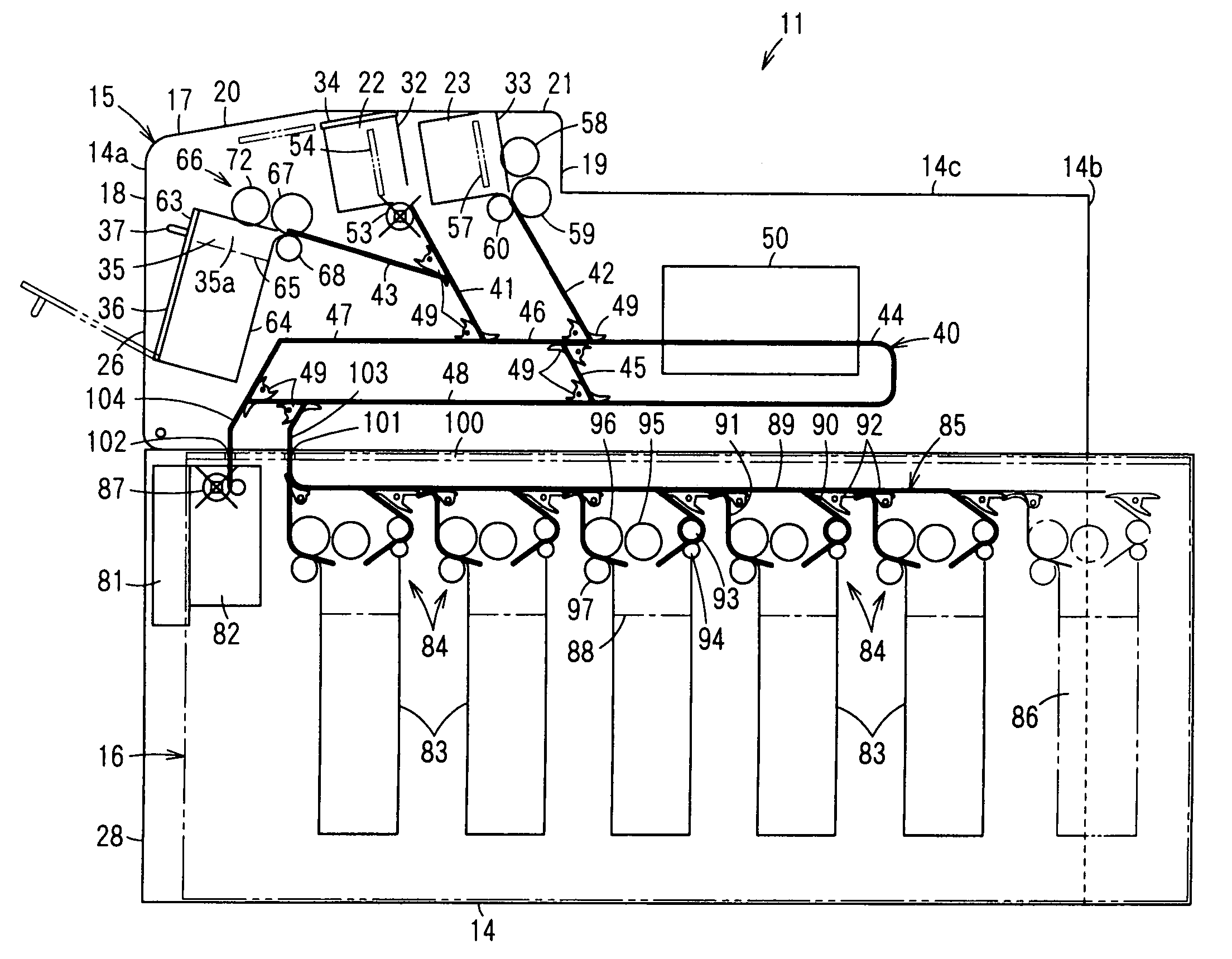
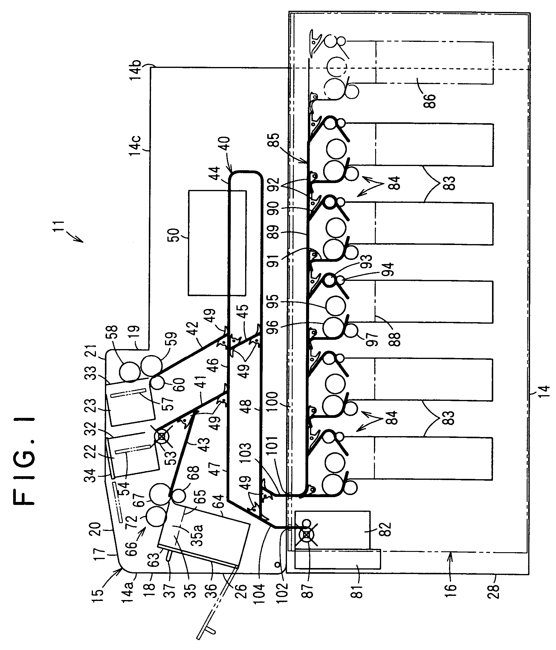
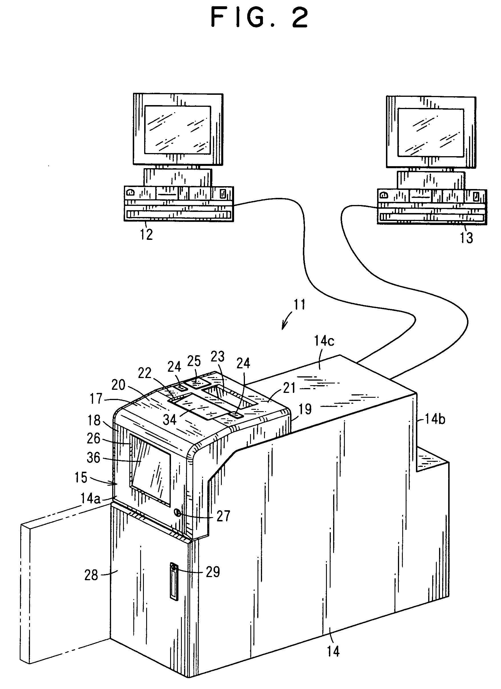
[0045] FIG. 2 shows a circulating type bank note depositing and dispensing machine 11. The circulating type bank note depositing and dispensing machine 11 is installed in the counter of, for example, a bank between two tellers inside the counter, and can be used by both or either one of the left and right tellers of the circulating type bank note depositing and dispensing machine 11.

[0046] High-order terminals 12 and 13 operated by the two left and right tellers are connected to the circulating type bank note depositing and dispensing machine 11. Three ways of using the circulating type bank note depositing and dispensing machine 11 are available, wherein the circulating type bank note depositing and dispensing machine 11 may be used by any one of the high-order terminals 12 and 13 or may be used by both sides thereof.

[0047] The circulating type bank note ...


PUM


Abstract

To provide a circulating type bank note depositing and dispensing machine 11, with which the progressing state of a depositing process and a dispensing process are made visible from a customer side, capable of quickening temporary storage of deposited bank notes and quickening and facilitating the return of the temporarily stored bank notes when the depositing is not approved. The bank note depositing port 23 and bank note dispensing port 22 are, respectively, disposed on the upper side of the machine body 14, and it becomes possible for a customer to observe or check the progressing state of a depositing process or a dispensing process. The temporary storage portion 35 of deposited bank notes is disposed in the front side area of the machine body 14, and the deposited bank notes are collectively and temporarily stored in the temporary storage portion 35 of deposited bank notes, wherein temporary storage of deposited bank notes is quickened. When the depositing is not approved, the front side door 36 of the temporary storage portion 35 is opened, the temporarily stored bank notes are collectively taken out from the front side of the machine body 14, and the return of the temporarily stored bank notes is quickened and facilitated.

Description

[0001] 1. Field of the Invention[0002] The present invention relates to a circulating type bank note depositing and dispensing machine by which deposited bank notes are used as bank notes to be dispensed.[0003] 2. Related Background Art[0004] Conventionally, there is a circulating type bank note depositing and dispensing machine that is disposed on the counter of a financial institution such as a bank, etc., and is commonly used as two tellers who are inside the counter, that is, a circulating type bank note depositing and dispensing machine that can be used by tellers existing at either side or both sides of the left and right sides of the circulating type bank note depositing and dispensing machine.[0005] In such a circulating type bank note depositing and dispensing machine, an upper structure unit, an intermediate structure unit and a lower structure unit are disposed on the upper section, intermediate section and lower section of the machine body, respectively. (For example, se...

Claims


Application Information

Patent Timeline
Patent Type & Authority Applications(United States)
IPC IPC(8): G07D9/00B65H31/34B65H83/02G07D11/00G07F19/00
CPCG07D11/0054G07F19/203G07F19/202G07F19/20B65H31/10B65H31/20B65H2404/725B65H2405/1124G07D11/24G07D2211/00
Inventor KOBAYASHI, TOSHIHIKOKOBAYASHI, HITOSHIYAMADA, MANABUMIZORO, TSUGUONAKATSUKA, SHIGEKI
Owner GLORY KOGYO KK
Why Eureka
Try Eureka