Degaussing coil holder

a degaussing coil and holder technology, applied in the direction of screws, magnetic bodies, television systems, etc., can solve the problems of deteriorating the quality of pictures displayed on the crt, requiring a complicated metal mold, and requiring a complex structur

Inactive Publication Date: 2004-07-15
ORION ELECTRIC CO LTD
View PDF6 Cites 2 Cited by
  • Summary
  • Abstract
  • Description
  • Claims
  • Application Information

AI Technical Summary

Problems solved by technology

Even though the TV set is completely adjusted, the residual magnetism affects somewhat the electron beam in its traveling direction, thereby deteriorating the quality of pictures displayed on the CRT.
The "Degaussing Coil Holder" is relatively complicated in structure, and accordingly it requires a complicated metal mold, which costs much.
This is a laborious work.
Neither the Degaussing Coil Fastening Structure nor the Coil Clamp permits the easy and quick attachment of the degaussing coil to the CRT.
The resultant displacement of the degaussing coil 7 and braid wire 12 may cause an adverse effect on their functions.

Method used


Image

  • Degaussing coil holder
  • Degaussing coil holder
  • Degaussing coil holder

Examples


first embodiment

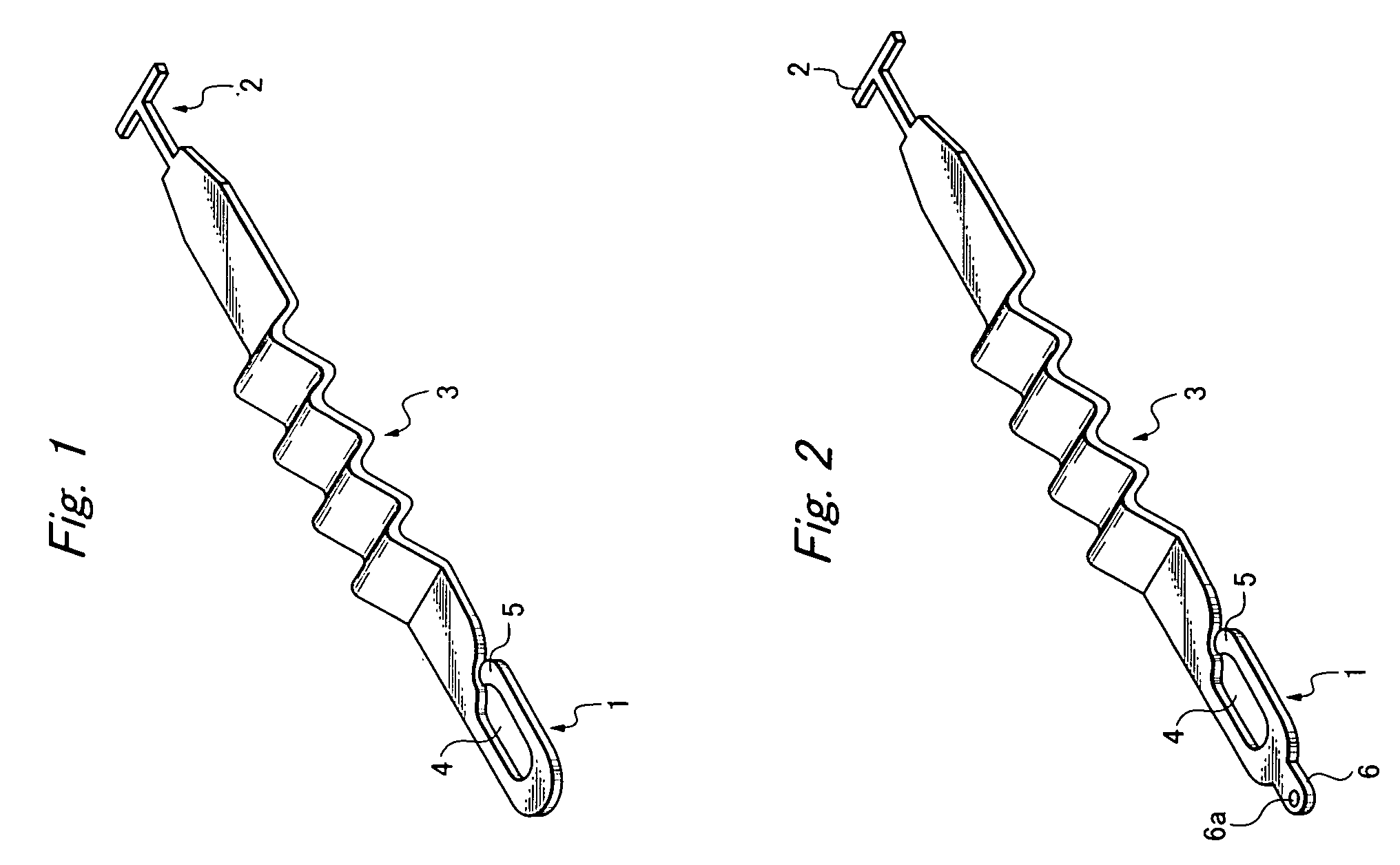
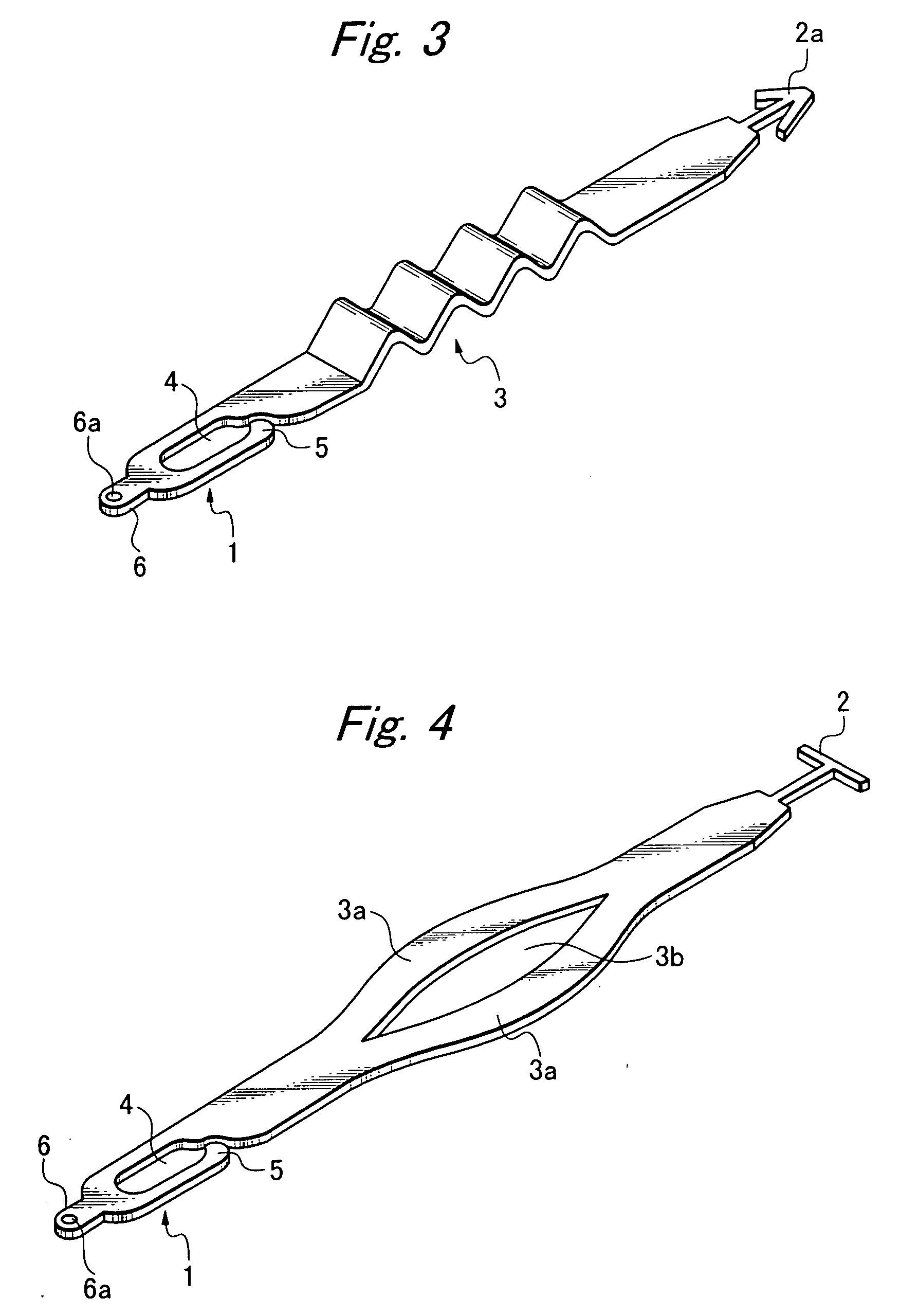
[0031] Referring to FIG. 1, a degaussing coil holder according to the invention is a linear resin mold comprising a hook 1, a catch 2, and an expandable strip 3 integrally connected at both ends to the hook 1 and the catch 2. The hook 1 is formed in a shape of the letter, "U", having a grip aperture 4 to let the degaussing coil 7 fit in. The hook end 5 can be twisted and raised to open the loop hole wide, so that the degaussing coil 7 may be pushed into the grip aperture 4 after passing through the so wide-opened loop hole.

[0032] The catch 2 is formed in a shape of the letter, "T", and it can be fixedly fit in a small hole 10, which is purposely made in the metal piece 9 for fastening the CRT to the cabinet (see FIG. 8). The expandable strip 3 takes a wavy form, and it is thin and flexible enough to yieldingly extend when the degaussing coil holder is stretched.

[0033] Referring to FIG. 2, a degaussing coil holder according to the second embodiment is different from the first embodim...

sixth embodiment

[0037] Referring to FIG. 6, a degaussing coil holder is a resin mold comprising a hook 1a, a "T"-shaped catch 2c, a resilient strip 3 integrally connected at both ends to the hook 1a and the catch 2c. The hook 1a is bent to be like a fishhook, and an engagement piece 6 is integrally connected to the hook 1a, projecting forward.

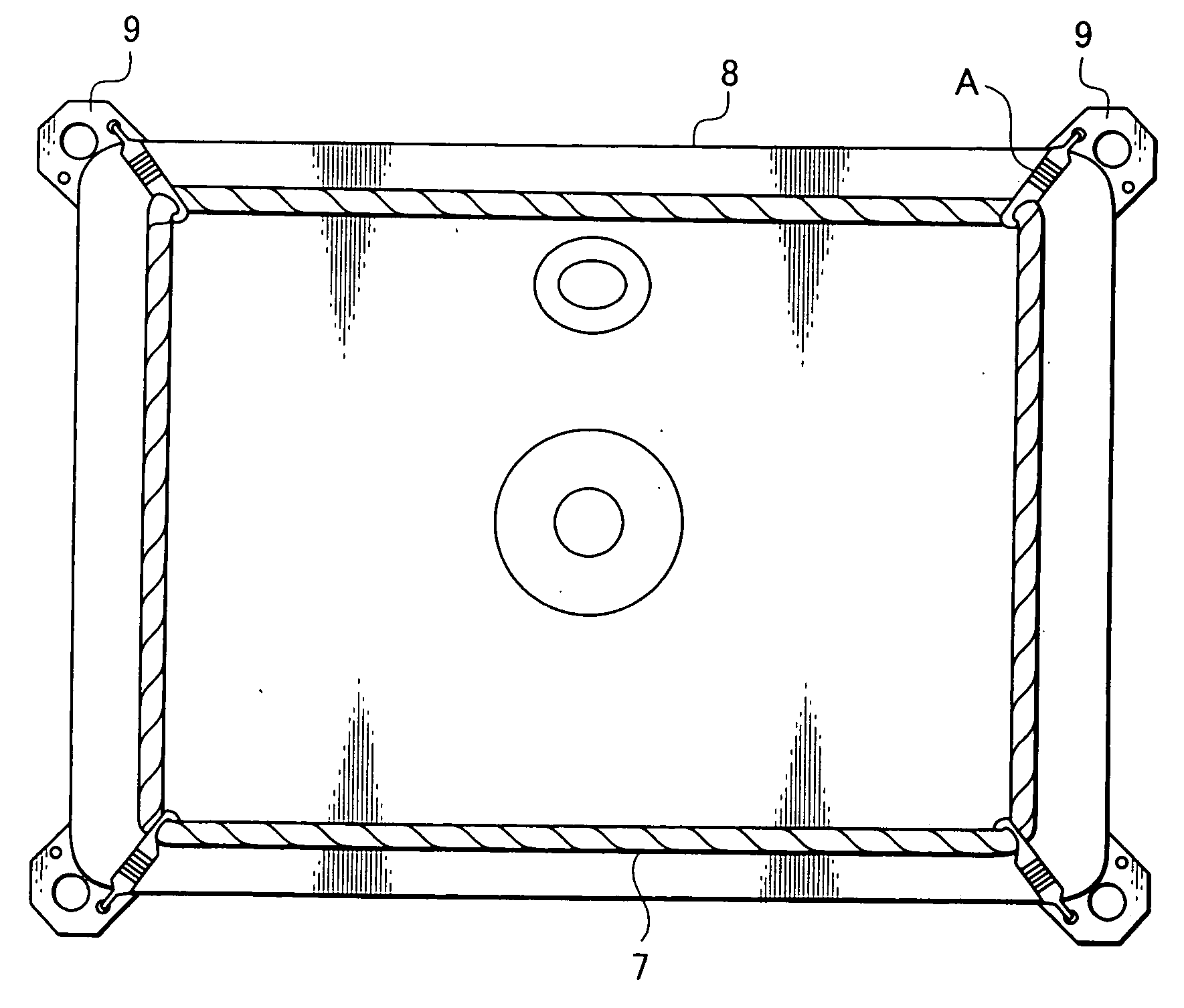
[0038] FIG. 7 illustrates how the degaussing coil 7 can be fastened with the degaussing coil holders "A" according to the first embodiment. The degaussing coil 7 is put around the CRT 8, and is pulled outwards by the holders "A" at four points. Referring to FIG. 8, the CRT 8 has fastening metals 9 fixed to its four corners, and each holder "A" is linked to the fastening metals 9 with the catch 2 caught in one of the opposite small holes 10, which are made in the CRT fastening metal 9. The "T"-shaped catch 10 is deformed into a linear, slender shape to be inserted in the small hole 10, and then, the so deformed catch is allowed to return to its original shape ...


PUM


Abstract

To provide a degaussing coil holder for fastening a degaussing coil around a cathode ray tube which is easy in use and capable of stretching and fastening the degaussing coil in position, it is made of a resin mold having a hook to hang the degaussing coil, a catch to fixedly fit in a small hole made in a selected CRT fastening metal and an expandable strip integrally connected at both ends to the hook and catch.

Description

[0001] 1. Field of the Invention[0002] The present invention relates to a degaussing coil holder for fastening a degaussing coil around a cathode ray tube (CRT).[0003] 2. Related Art[0004] The CRT is equipped with a shadow mask of a metal such as iron, and therefore the CRT is liable to be magnetized by a selected component of the geomagnetism, which component runs in the same direction, as the CRT is set. Even though the TV set is completely adjusted, the residual magnetism affects somewhat the electron beam in its traveling direction, thereby deteriorating the quality of pictures displayed on the CRT. It is, therefore, necessary that the shadow mask be demagnetized whenever the TV set is changed in position. For the purpose the degaussing coil is attached to the CRT.[0005] In order to improve the efficiency with which degaussing coils can be attached to CRTs and to reduce the cost involved for assembling, a variety of degaussing coil holders have been hitherto proposed. JP 2001-28...

Claims


Application Information

Patent Timeline
Patent Type & Authority Applications(United States)
IPC IPC(8): H01H47/00H01J29/00
CPCH01J29/003
Inventor SHIMIZU, KAZUYUKIHARADA, TOMOYUKIKOBASHI, MASAKUNI
Owner ORION ELECTRIC CO LTD
Why Eureka
Try Eureka