Display apparatus, method and program

a technology of display apparatus and display device, applied in the field of display device, method and program, can solve the problems of image deterioration, image deterioration, image deterioration, and oblique lines in characters, photographs or complicated drawings

Inactive Publication Date: 2004-07-29
PANASONIC CORP
View PDF4 Cites 109 Cited by
  • Summary
  • Abstract
  • Description
  • Claims
  • Application Information

AI Technical Summary

Benefits of technology

[0018] This prevents a color drift from occurring by effectively performing a filtering on an area having a prominent color value, and at the same time preventing image quality deterioration due to accumulation of the smooth-out effect, thus providing a high-quality image display with the accuracy of sub-pixel.

Problems solved by technology

However, when images are displayed in units of pixels on a small-sized, low-resolution screen of, for example, a mobile telephone or a mobile computer, oblique lines in characters, photographs or complicated drawings look shaggy.
However, when the sub-pixels are smoothed-out in luminance, the image become dim.
This is another problem of image deterioration.
The more the superimposition of an image or the filtering is performed on a same image, the more degraded the image quality is.
As described above, display apparatuses for displaying high-quality images in units of sub-pixels have a problem of image quality degradation that becomes prominent when sub-pixel luminance is smoothed out a plurality of times.

Method used


Image

  • Display apparatus, method and program
  • Display apparatus, method and program
  • Display apparatus, method and program

Examples


embodiment 2

[0162] Embodiment 2

[0163] General Outlines

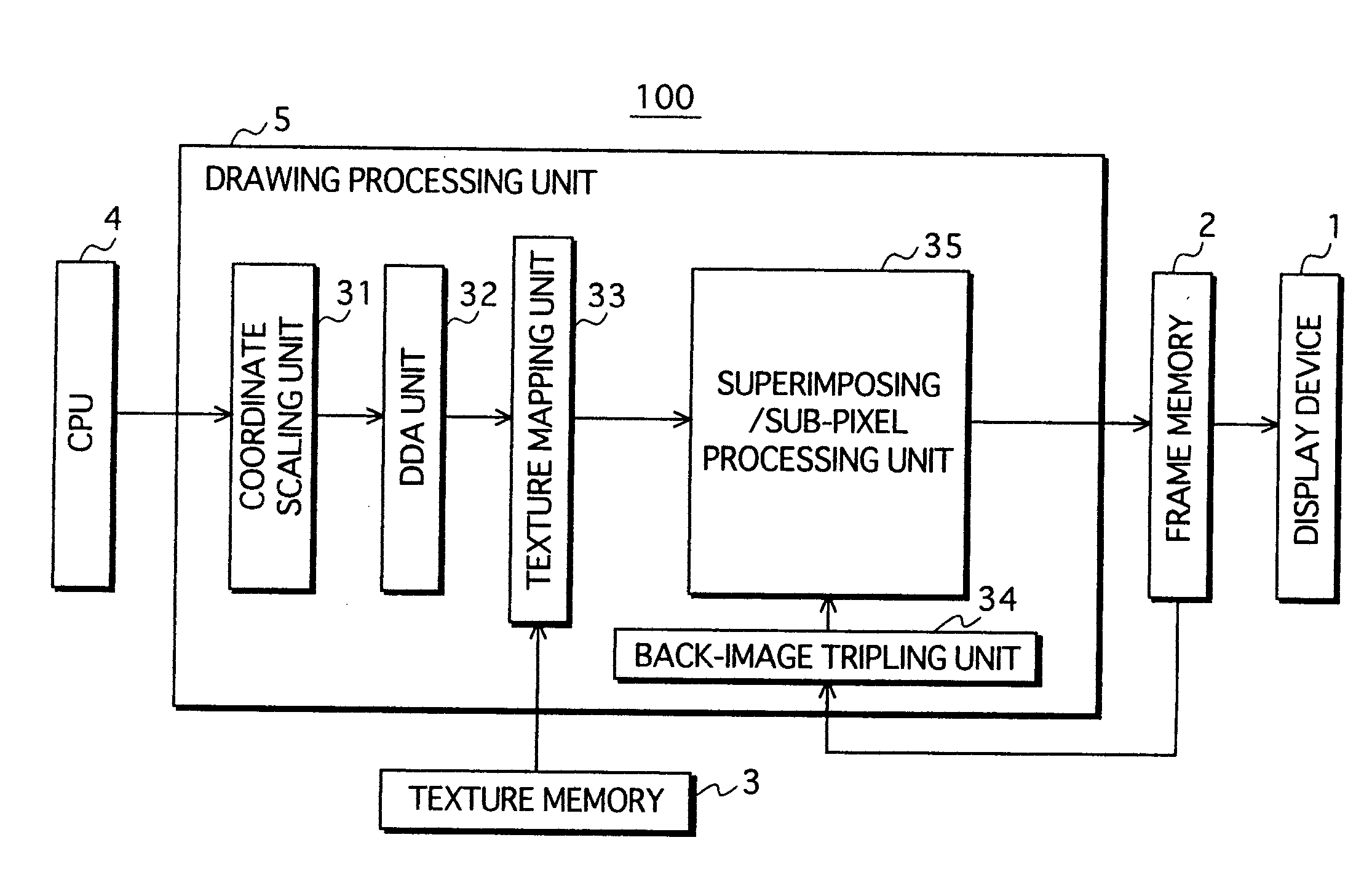
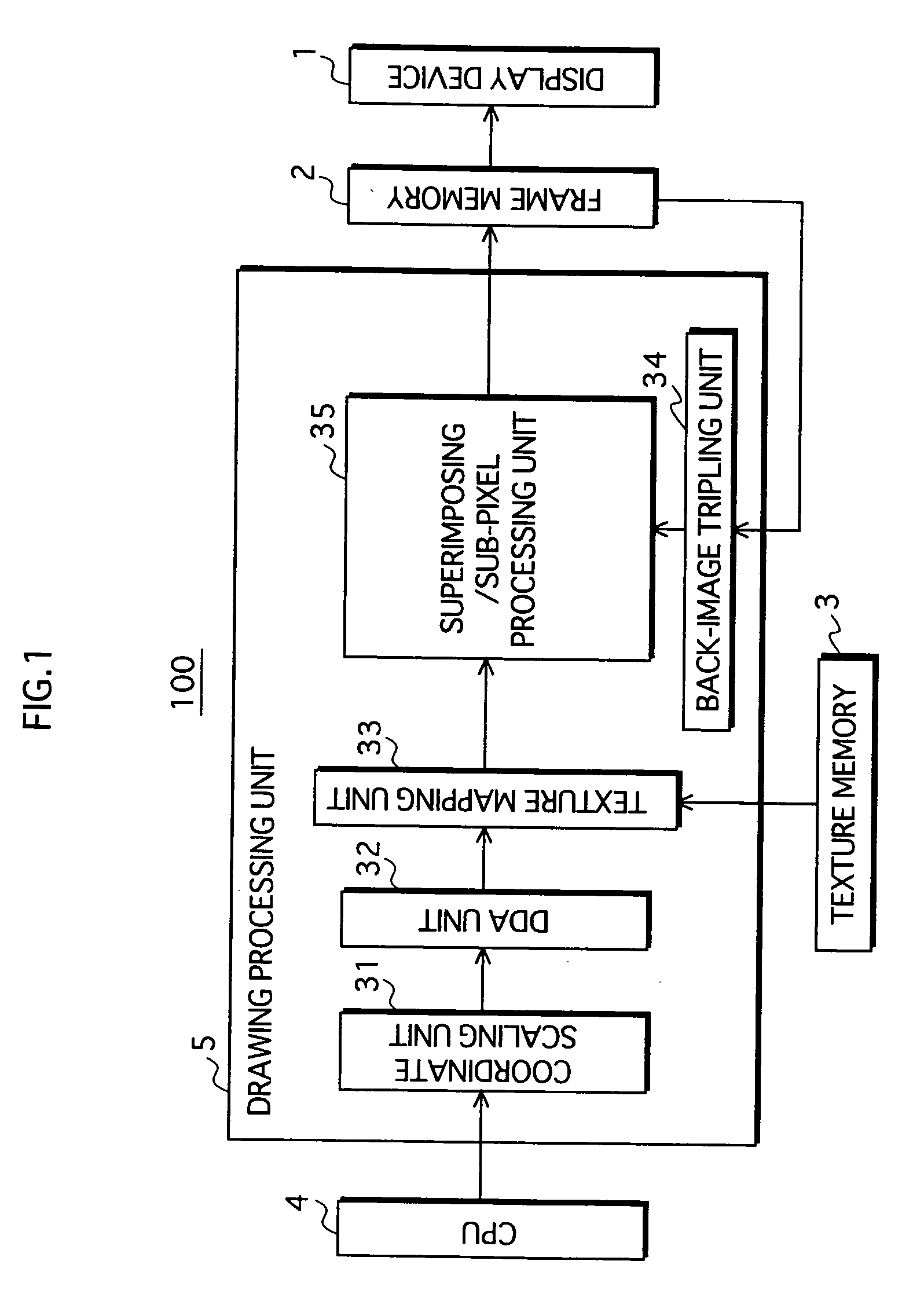
[0164] In Embodiment 1, the display apparatus 100 judges on the necessity of the filtering process based on the dissimilarity level of each sub-pixel to the surrounding sub-pixels in the front image so that the area of the composite image that overlaps the back image and is subject to the filtering process is limited to a small area. In Embodiment 2, the display apparatus varies the degree of the smooth-out effect provided by the filtering process according to the dissimilarity level of each sub-pixel to the surrounding sub-pixels in the front image, for a similar purpose of reducing the accumulation of the smooth-out effect to provide a high-quality image display with the accuracy of sub-pixel.

[0165] Construction

[0166] FIG. 13 shows the construction of the display apparatus 200 in Embodiment 2 of the present invention. As shown in FIG. 13, the display apparatus 200 has the same construction as the display apparatus 100 except for a superimp...


PUM


Abstract

A display apparatus that displays a composite image of a front image and a back image. The display apparatus includes: a front-image change detecting unit 42 that detects a difference in a visual characteristic between a sub-pixel and the surrounding sub-pixels in a front image; a filtering necessity judging unit 43 that judges for each sub-pixel in the front image whether a sub-pixel should be subject to the filtering process or not, based on the degree of the detected difference; and a filtering unit 45 that performs the filtering process only on sub-pixels in the composite image that correspond to the sub-pixels that have been judged as having to be subject to the filtering process.

Description

[0001] (1) Field of the Invention[0002] The present invention relates to a technology for displaying high-quality images on a display device which includes a plurality of pixels each of which is an alignment of three luminous elements for three primary colors.[0003] (2) Description of the Related Art[0004] Among various types of display apparatuses, there are some types, such as LCD (Liquid Crystal Display) or PDP (Plasma Display Panel), that include a display device having a plurality of pixels each of which is an alignment of three luminous elements for three primary colors R, G and B (red, green and blue), where the pixels are aligned to form a plurality of lines, and the luminous elements are called sub-pixels.[0005] In general, images are displayed in units of pixels. However, when images are displayed in units of pixels on a small-sized, low-resolution screen of, for example, a mobile telephone or a mobile computer, oblique lines in characters, photographs or complicated drawi...

Claims


Application Information

Patent Timeline
Patent Type & Authority Applications(United States)
IPC IPC(8): G06T11/60G09G3/20G09G3/36G09G5/02G09G5/28G09G5/36G09G5/377
CPCG09G3/20G09G3/2003G09G5/02G09G2340/10G09G2320/103G09G2340/0457G09G5/28
Inventor TAOKA, HIROKITEZUKA, TADANORI
Owner PANASONIC CORP
Why Eureka
Try Eureka