Silo unloader

Inactive Publication Date: 2004-07-29
HANSON SILO
View PDF7 Cites 22 Cited by
  • Summary
  • Abstract
  • Description
  • Claims
  • Application Information

AI Technical Summary

Problems solved by technology

'977 patent was found to be a considerable improvement over the prior art in the way that the auger arm was configured to break up compacted and sometimes frozen silage, the use of the blower to move the lo

Method used


Image

  • Silo unloader
  • Silo unloader
  • Silo unloader

Examples


Embodiment Construction

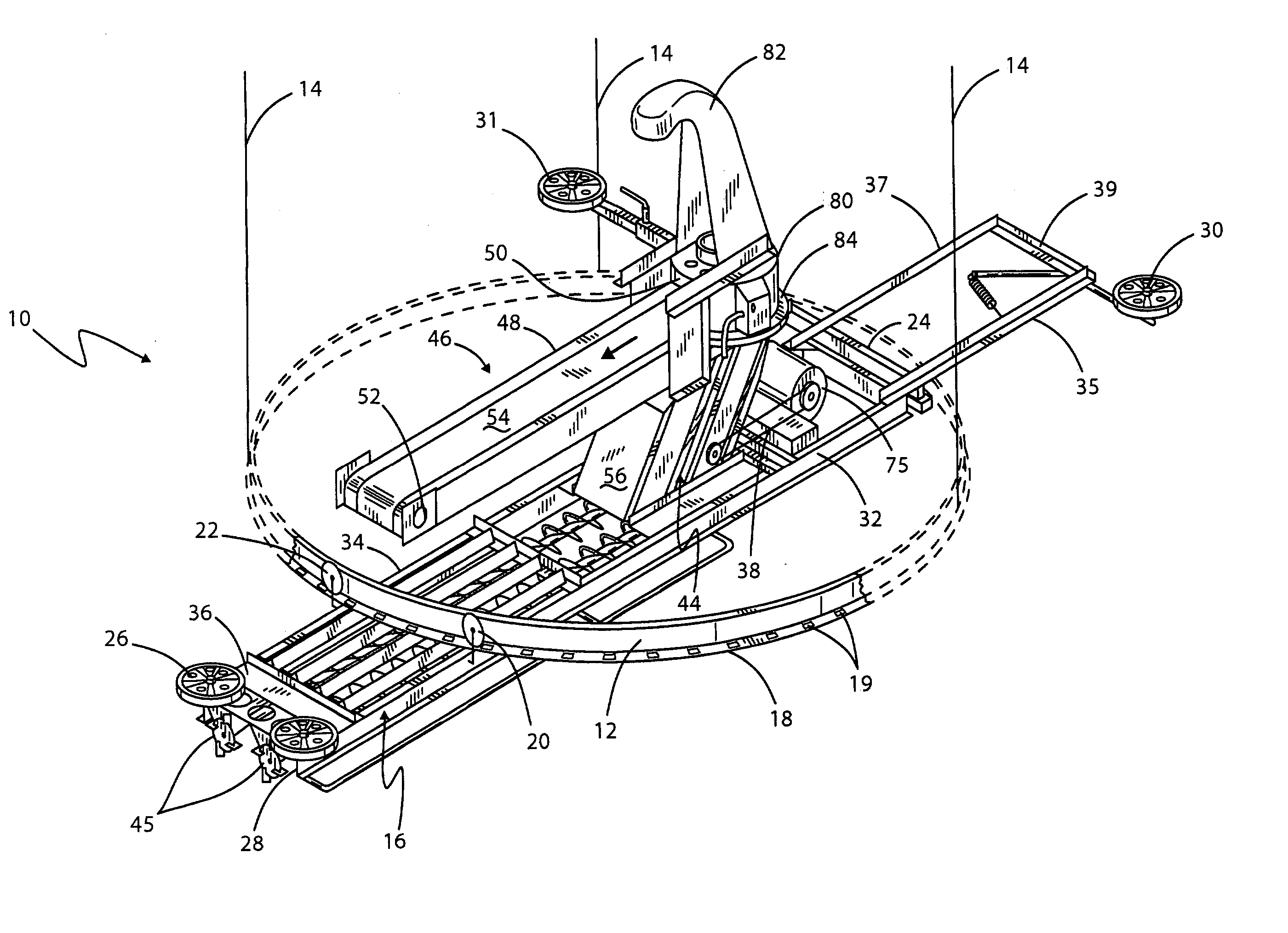
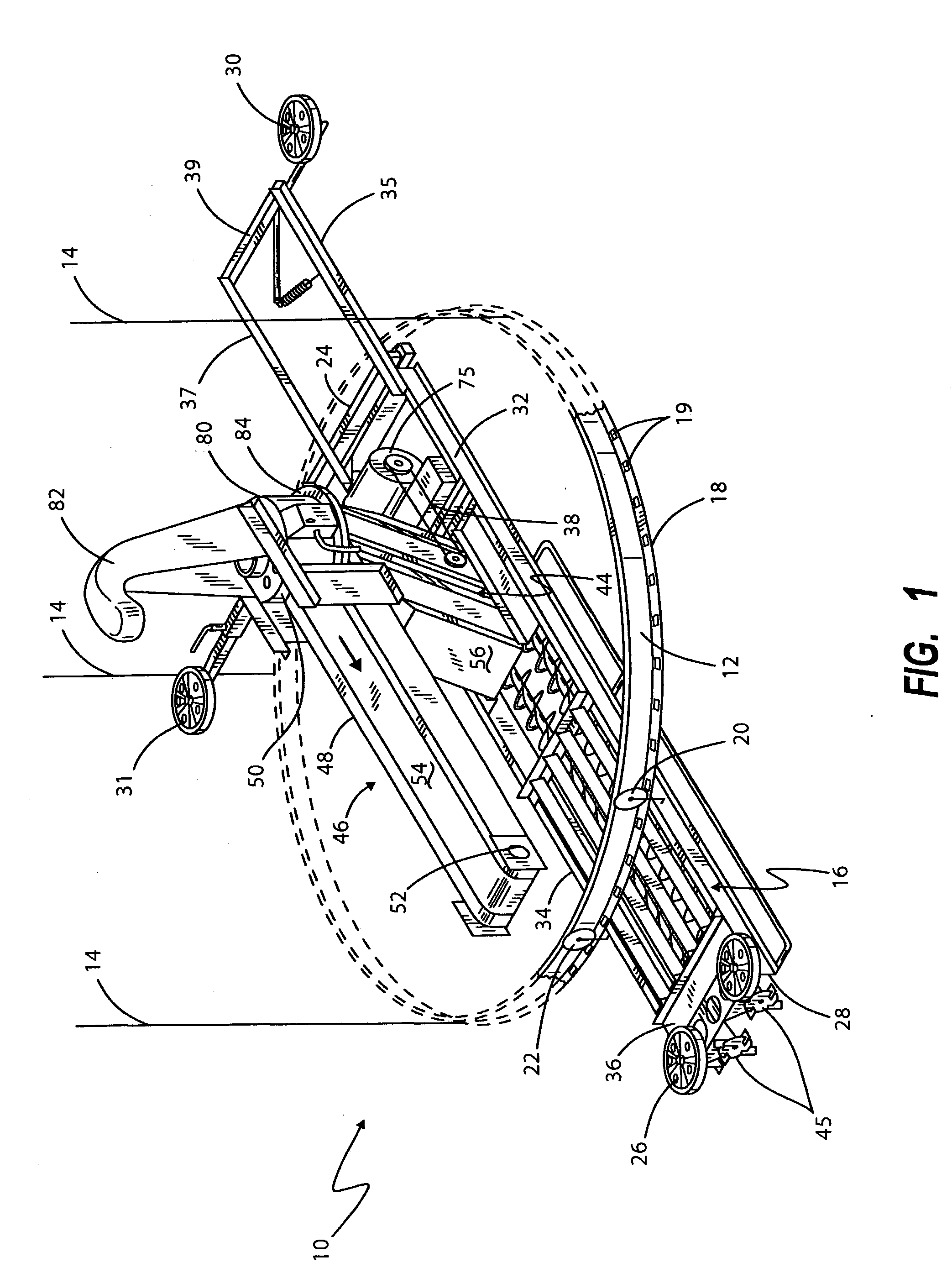
[0014] As those skilled in the art appreciate, a silo unloader is adapted to be placed in the interior of a cylindrical tower silo in which a silage crop is stored. Over time, due to its own weight and due to decomposition of the vegetable material, the silage stored becomes compacted and melded within the silo. When it is desired to retrieve silage from the silo to feed to cattle or the like, a silo unloader is used to remove quantities of silage from the top surface thereof and feed it through a selected one of a plurality of vertically aligned drop chute openings in the silo wall. Once ejected through the opening, it falls through the chute to the ground to be fed to cattle.

[0015] The silo unloader is indicated generally by numeral 10 and it is seen to include a rotational guide ring 12 that is adapted to be secured by cables 14 and pulleys and then down to a winch (not shown) that is secured at the bottom of the tower silo whereby the entire assembly 10 can be periodically lower...


PUM


Abstract

The silo unloader having one or more augers journaled for rotation therein is arranged to travel in a circular manner within a tower silo to auger silage to a collection point at the center thereof. Located proximate the central collection point is a transfer conveyor comprising two vertically oriented snowmobile track assemblies arranged to have corresponding flights of the track belt engaged with one another. As the tracks are driven by an electric motor, silage becomes entrained between the two adjacent tracks and is propelled therealong onto a discharge conveyor that leads to a drop chute opening in the wall of the silo.

Description

Background of the Invention[0001] I. Field of the Invention[0002] This invention relates generally to a machine for removing silage from a tower silo, and more particularly to a silo unloader having an improved transfer assembly for moving silage from a collection point proximate the center of the tower silo to a discharge conveyor leading to a drop chute opening in the silo wall.[0003] II. Discussion of the Prior Art[0004] In the Hanson et al. U.S. Pat. No. 5,642,977, the contents of which are incorporated herein by reference, there is described a silo unloader having a stationary frame that is adapted to be suspended from the top of the silo which can be lowered as the silage is removed. The frame includes a relatively large diameter guide ring from which an auger arm is suspended and means are provided for rotating the auger arm in a horizontal plane to sweep out a circular path. Contained within the auger arm is a pair of augers that are adapted to dig into the compacted top lay...

Claims


Application Information

Patent Timeline
IPC IPC(8): A01F25/20B65G15/14B65G65/38
CPCA01F25/2009B65G65/38B65G15/14
Inventor HANSON, GREGG W.JACOBSON, HOWARD D.
Owner HANSON SILO
Why Eureka
Try Eureka