System for decoupling a fan from a turbojet by means of an explosive charge

a technology of explosive charge and turbojet, which is applied in the direction of liquid fuel engines, machines/engines, launching weapons, etc., can solve the problems of significant damage, high level of unbalance, and the decoupling system still presents, so as to eliminate all uncertainties and mitigate the drawbacks

Active Publication Date: 2004-08-19
SN DETUDE & DE CONSTR DE MOTEURS DAVIATION S N E C M A
View PDF3 Cites 5 Cited by
  • Summary
  • Abstract
  • Description
  • Claims
  • Application Information

AI Technical Summary

Benefits of technology

0006] The present invention thus seeks to mitigate those drawbacks by proposing a reliable system for decoupling the fan of a turbojet, which makes it possible to eliminate all uncertainty as to the moment at which link...

Problems solved by technology

Under extreme circumstances, such as losing a blade, a high level of unbalance is generated.
Such unbalance gives rise to cyclical loading and vibration, which the bearings supporting the fan drive shaft communicate to the stationary portions of the turbojet, with significant risk of damage.
Such a d...

Method used


Image

  • System for decoupling a fan from a turbojet by means of an explosive charge
  • System for decoupling a fan from a turbojet by means of an explosive charge
  • System for decoupling a fan from a turbojet by means of an explosive charge

Examples


Embodiment Construction

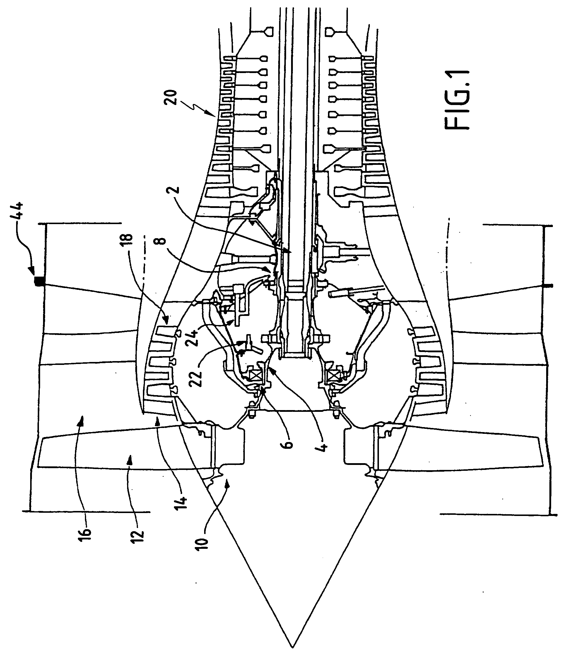
[0015] Reference is made initially to FIG. 1 which shows part of a turbojet in longitudinal section.

[0016] The turbojet is constituted in particular by a low pressure shaft 2, and more precisely a fan drive shaft 4 mounted on a front bearing 6 and a rear bearing 8. At its front end, the shaft 4 carries a fan 10 fitted with a plurality of blades 12 extending radially in front of the inlet to an inner gas stream 14 and the inlet to an outer stream 16 surrounding the inner stream. In the inner stream 14, the turbojet further comprise a low-pressure compressor 18 followed by a high-pressure compressor 20 situated downstream therefrom. Lubrication ducts 22 and 24 connected to pumps (not shown) serve to inject oil into the bearings 6 and 8.

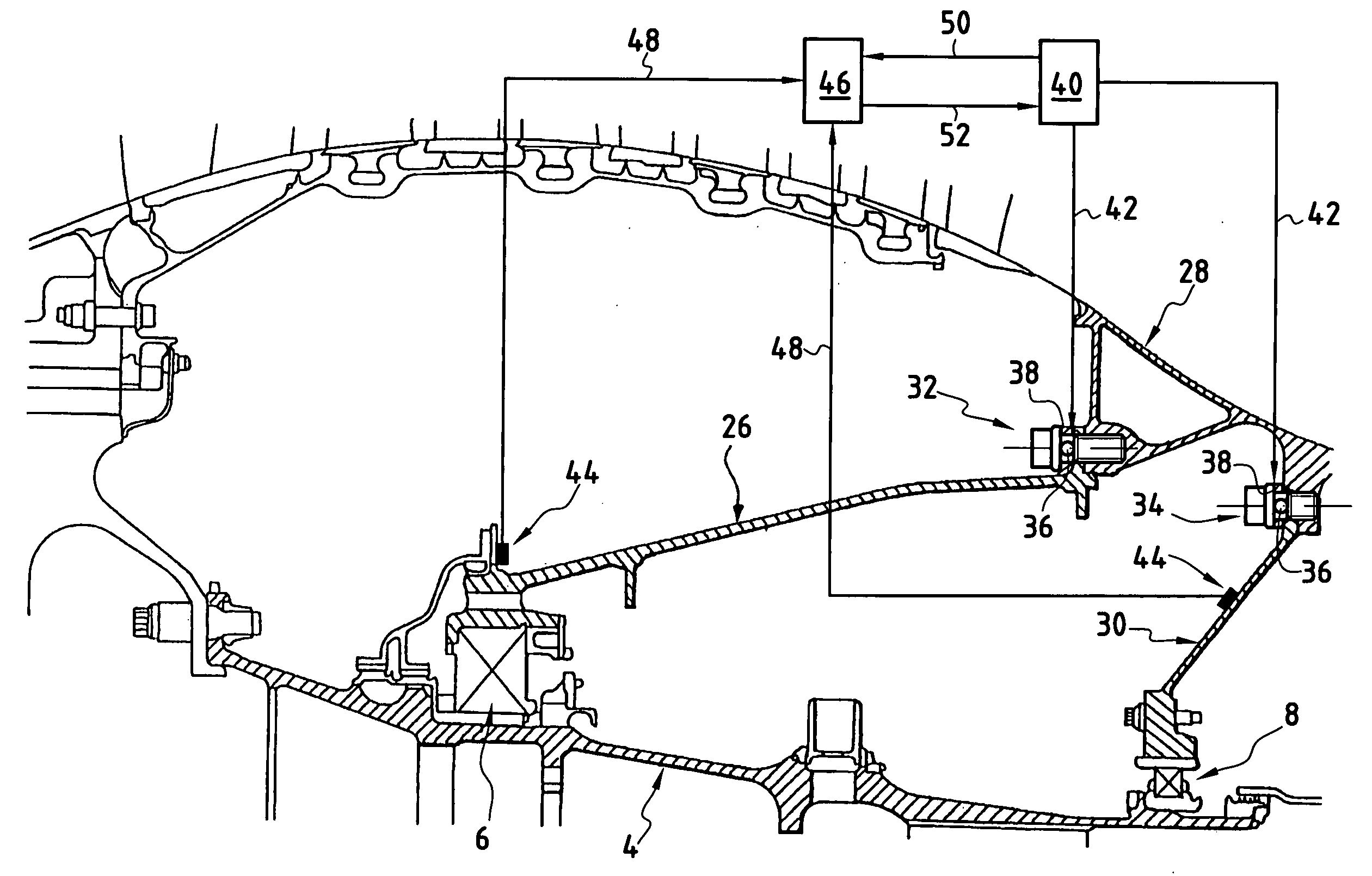
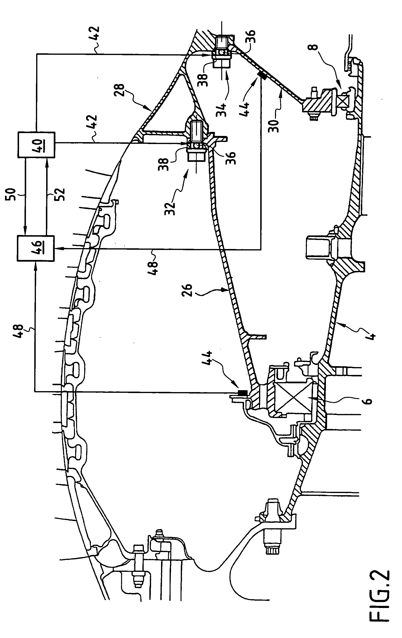
[0017] In FIG. 2, it can be seen that the front bearing 6 is supported by a front bearing support 26 which is connected to part of the stationary structure 28 of the turbojet. Similarly, the rear bearing 8 is supported by a rear bearing support 30 which...


PUM


Abstract

A system for decoupling a fan of a turbojet, the turbojet including a moving fan shaft mounted on bearings each connected to a stationary structure of the turbojet by bearing supports, the bearing supports being fixed to the stationary structure of the turbojet via mechanical links serving, during normal operation of the turbojet, to transmit the forces generated by rotation of the fan, the mechanical links include explosive charges enabling the links to be broken, the explosive charges being controlled by a full authority digital engine control computer on the basis of means for measuring the mechanical stresses in the turbojet and of a computer model simulating the static, dynamic, and thermodynamic behavior of the turbojet.

Description

[0001] The present invention relates to the general field of systems for fixing a fan to a turbojet. It relates more particularly to a system for decoupling a fan from a turbojet in the event of large forces on the fan support.[0002] In flight, a turbojet receives air through a fan. The fan serves to compress a quantity of this air which contributes to the thrust from the turbojet. It comprises a plurality of blades which perform said compression and it is set into rotation by a turbine via a drive shaft. The drive shaft is mounted on bearings which are connected to stationary portions of the turbojet.[0003] Under extreme circumstances, such as losing a blade, a high level of unbalance is generated. Such unbalance gives rise to cyclical loading and vibration, which the bearings supporting the fan drive shaft communicate to the stationary portions of the turbojet, with significant risk of damage.[0004] In order to provide some protection against such danger, it is generally possible ...

Claims


Application Information

Patent Timeline
IPC IPC(8): B64D1/00B64D27/26F01D21/04F01D25/16F02C7/00F04D29/34F04D29/60F16P5/00
CPCF01D21/045F16P5/005F01D25/16
Inventor BINETRUY, GABRIELDESINDES, JEAN-MARIEKERVISTIN, ROBERT
Owner SN DETUDE & DE CONSTR DE MOTEURS DAVIATION S N E C M A
Why Eureka
Try Eureka