Modeling and calibrating a three-port time-domain reflectometry system

a time-domain reflectometry and three-port technology, applied in the field of time-domain reflectometry, can solve the problems of imperfect knowledge, distorted information-bearing tdr signals, and components used may not be as high as dedicated tdr systems, and achieve the effect of effective conversion

Inactive Publication Date: 2005-01-11
AVAGO TECH WIRELESS IP SINGAPORE PTE
View PDF5 Cites 33 Cited by
  • Summary
  • Abstract
  • Description
  • Claims
  • Application Information

AI Technical Summary

Benefits of technology

Identifying, measurizing and characterizing the condition of a transmission line is a key element of any Digital Subscriber Line (DSL) deployment. In cases where the transceiver connection is not performing as expected, for example, the data rate is low, there are many bit errors, a data link is not possible, or the like, it is important to be able to identify characteristics about the loop including the length of the loop, and the existence, location and length of any bridged taps without having to send a technician to a rem

Problems solved by technology

An artifact of these components is that information-bearing TDR signals are distorted as they pass through these components.
This is especially an issue when the TDR system is implemented in a DSL transceiver utilizing the DSL transceiver front-end.
For example, DSL transceivers are consu

Method used


Image

  • Modeling and calibrating a three-port time-domain reflectometry system
  • Modeling and calibrating a three-port time-domain reflectometry system
  • Modeling and calibrating a three-port time-domain reflectometry system

Examples


Embodiment Construction

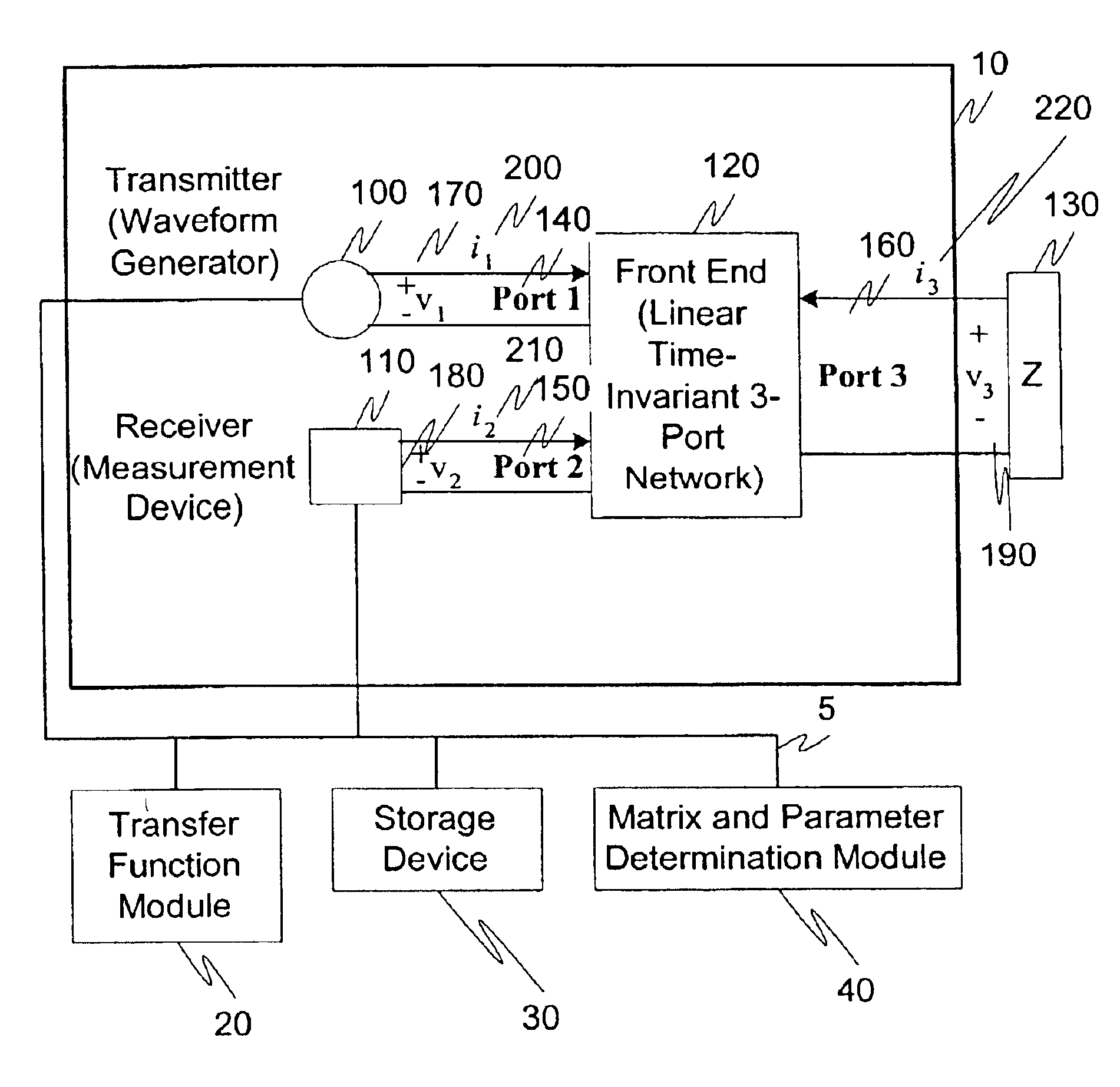
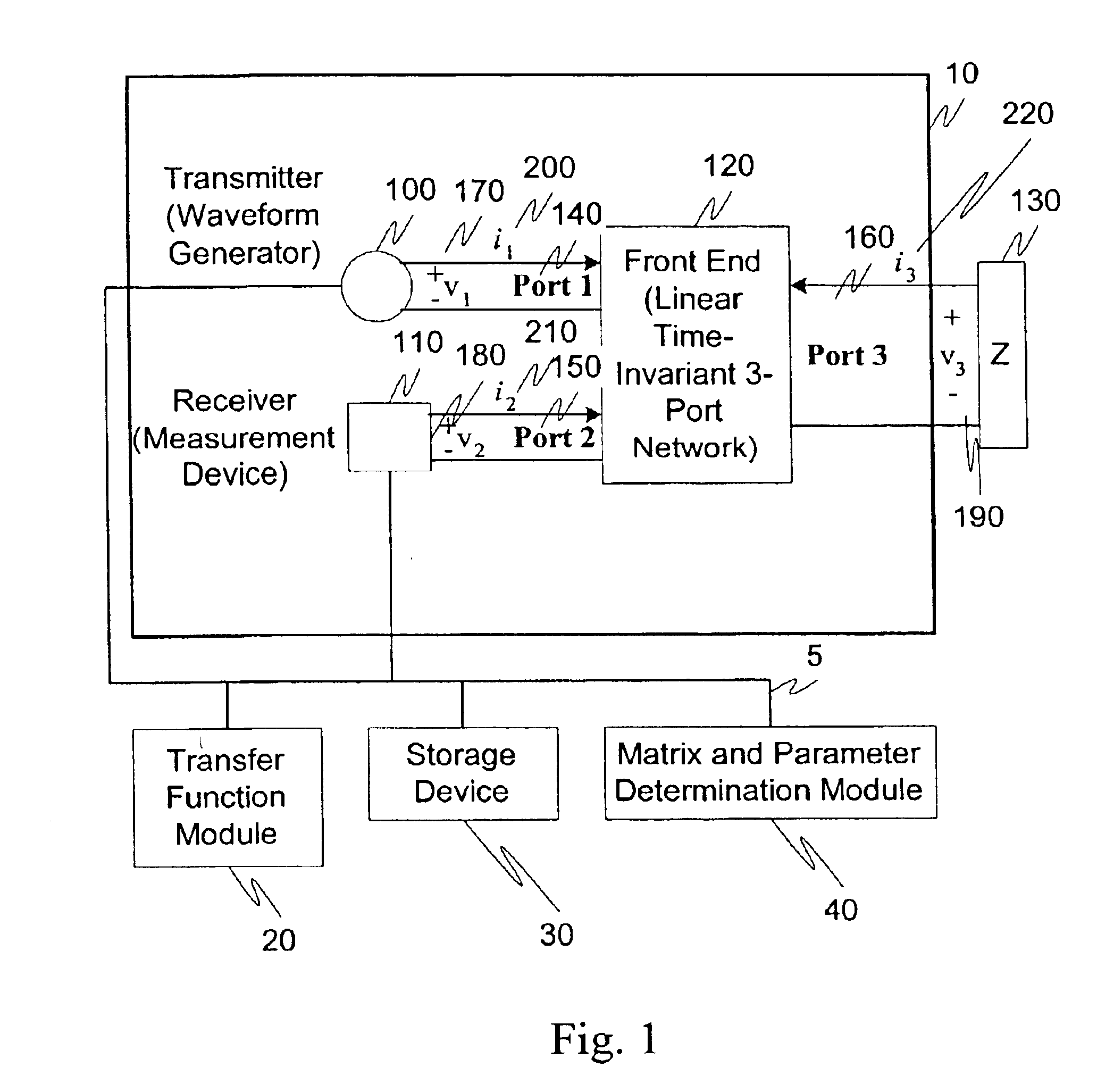
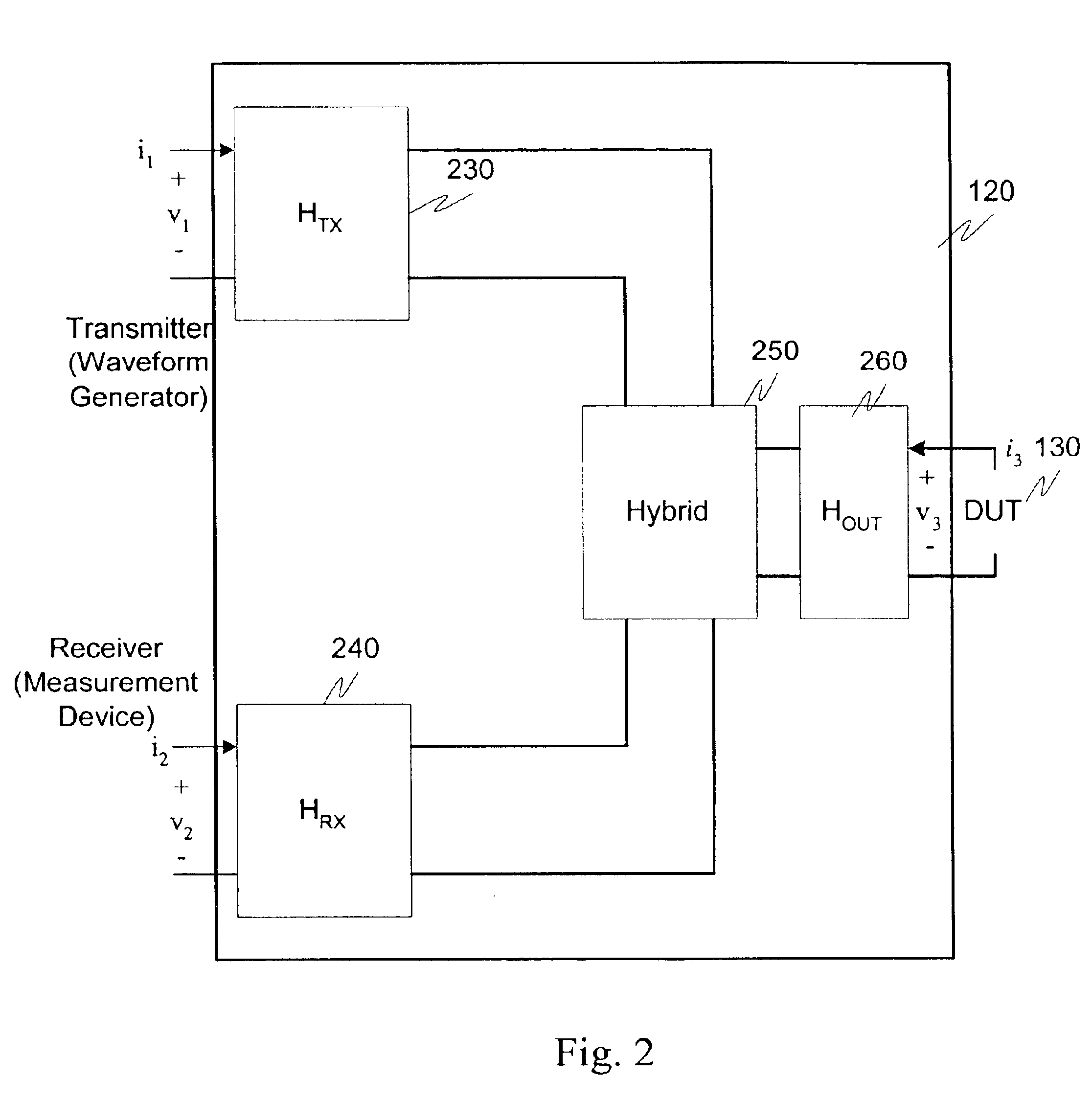
The exemplary embodiments of this invention will be described in relation to the application of a model to describe the TDR front-end an a method for determining the parameters of the model. However, it should be appreciated, that in general, the systems and methods of this invention will work equally well for modeling any linear, and time-invariant three port TDR system.

The exemplary systems and methods of this invention will also be described in relation to a TDR system that can be used in conjunction with a DUT such as a twisted-pair transmission line. However, to avoid unnecessarily obscuring the present invention, the following description omits well-known structures and devices that may be shown in block diagram form or otherwise summarized.

For the purposes of explanation, numerous details are set forth in order to provide a thorough understanding of the present invention. It should be appreciated however, that the present invention may be practiced in a variety of ways beyond...


PUM


Abstract

A three-port TDR front end comprises numerous components. An exemplary three-port TDR front end is a DSL modem. Information-bearing TDR signals are distorted as they pass through these components. With a perfect model of the response of its front-end, a TDR system usually can compensate for the effects of its front-end. In reality, however, the electrical characteristics of each component vary from design-to-design, board-to-board, and slowly over time. The result is imperfect knowledge about the true response of the front-end, errors in the model of the front-end, and degraded TDR performance. At least for this reason it is important to precisely calibrate the response of the TDR front-end through the use of a TDR modeling system.

Description

BACKGROUND OF THE INVENTION1. Field of the InventionThis invention generally relates to time-domain reflectometry. In particular, this invention relates to systems and methods for calibrating a time-domain reflectometer to precisely determine the reflectometer's response when connected to an electrical network.2. Description of Related ArtTime-domain reflectometry (TDR) systems use electrical measurements to estimate the physical structure and electrical nature of a conducting medium, which will be referred to herein as the Device Under Test (DUT). An example of a DUT is a twisted pair subscriber line, which comprises one or more interconnected electrical transmission lines generally having unknown terminations. Features of the DUT that can be estimated include the length of the line, the existence of bridged taps, the bridged tap locations, the bridged tap lengths, changes in gauge, terminations, and the like. Exemplary DUTs, such as subscriber lines, are constructed of twisted pai...

Claims


Application Information

Patent Timeline
IPC IPC(8): H04B3/46
CPCG01R27/32H04B3/493H04B3/46
Inventor BELGE, MURATCUNNINGHAM, CHRISTOPHER C.
Owner AVAGO TECH WIRELESS IP SINGAPORE PTE
Why Eureka
Try Eureka