Multiprocessor system capable of efficiently debugging processors

a multi-processor system and processor technology, applied in error detection/correction, instruments, digital computer details, etc., can solve the problems of increasing cost and requiring a long debugging tim

Inactive Publication Date: 2004-08-19
RENESAS TECH CORP
View PDF10 Cites 11 Cited by
  • Summary
  • Abstract
  • Description
  • Claims
  • Application Information

AI Technical Summary

Benefits of technology

[0011] An object of the present invention is to obtain a multiprocessor system that is capable of efficiently debugging a plurality of processors, while allowing cost reduction.

Problems solved by technology

According to the first conventional multiprocessor system, providing additional processors requires adding corresponding sets of debugging terminals and corresponding debugging devices, leading to an increase in cost.
According to the second conventional multiprocessor system, the debugging is always applied serially to all processors through all TAP controllers, requiring a long debugging time.

Method used


Image

  • Multiprocessor system capable of efficiently debugging processors
  • Multiprocessor system capable of efficiently debugging processors
  • Multiprocessor system capable of efficiently debugging processors

Examples


first preferred embodiment

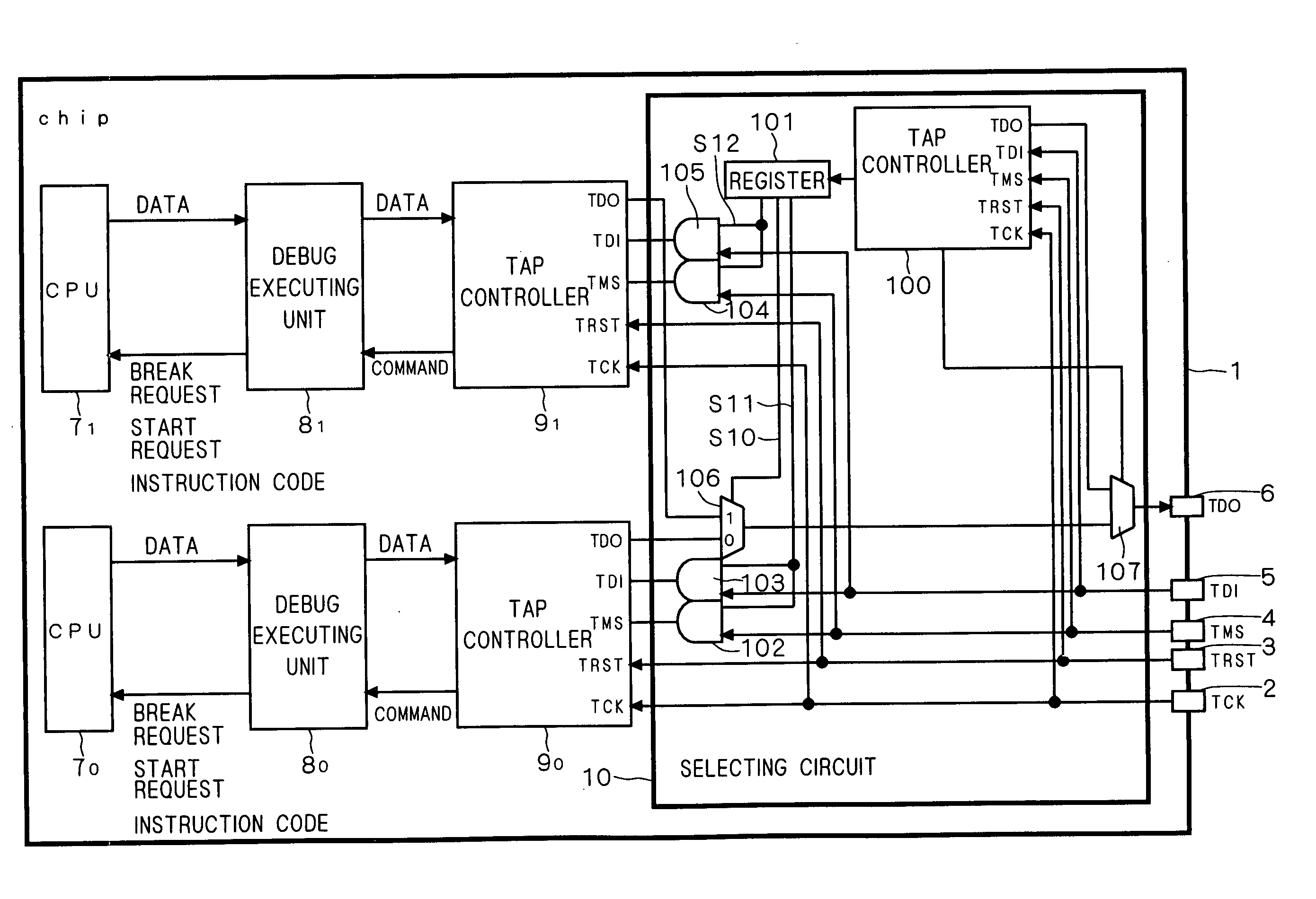
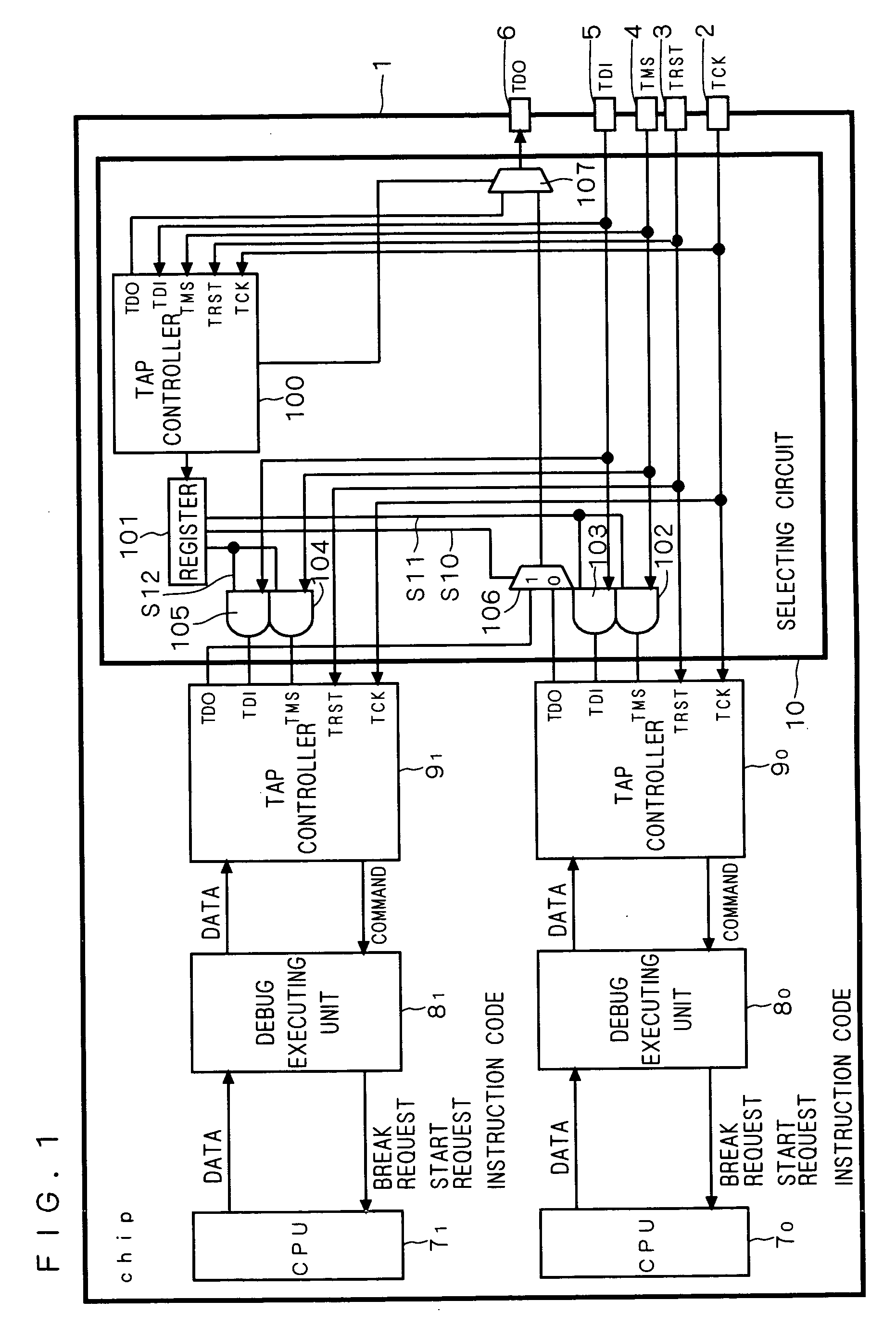
[0025] FIG. 1 is a block diagram showing the configuration of a multiprocessor system according to a first preferred embodiment of the invention. A chip 1 has a plurality of CPUs 7.sub.0 and 7.sub.1, debug executing units 8.sub.0 and 8.sub.1 for executing the debugging of the CPUs 7.sub.0 and 7.sub.1, TAP controllers 9.sub.0 and 9.sub.1 for controlling the debug executing units 8.sub.0 and 8.sub.1, a selecting circuit 10 for selecting, from the CPUs 7.sub.0 and 7.sub.1, at least one CPU to be debugged, and a single set of terminals, including terminals 2 to 6. The CPUs 7.sub.0 and 7.sub.1 are connected respectively to the debug executing units 8.sub.0 and 8.sub.1, and the debug executing units 8.sub.0 and 8.sub.1 are connected respectively to the TAP controllers 9.sub.0 and 9.sub.1. The selecting circuit 10 is connected between the TAP controllers 9.sub.0, 9.sub.1 and the terminals 2 to 6. The terminals 2 to 6 are connected to a debugging device (not shown), such as an ICE that conf...

second preferred embodiment

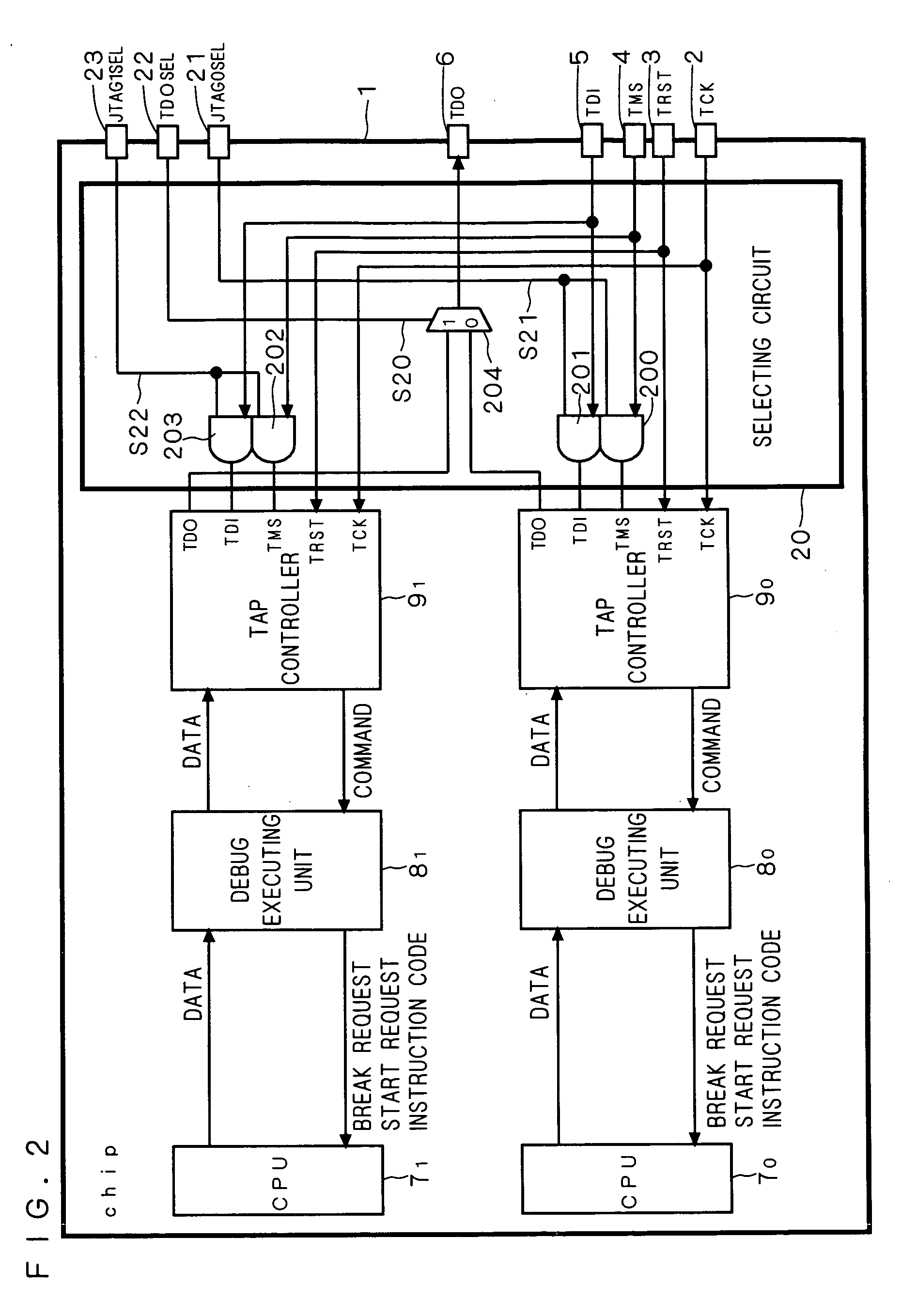
[0039] FIG. 2 is a block diagram showing the configuration of a multiprocessor system according to a second preferred embodiment of the invention. A chip 1 has CPUs 7.sub.0 and 7.sub.1, debug executing units 8.sub.0 and 8.sub.1, TAP controllers 9.sub.0 and 9.sub.1, a selecting circuit 20 for selecting, from the CPUs 7.sub.0 and 7.sub.1, at least one CPU to be debugged, terminals 2 to 6, and terminals 21 to 23.

[0040] The selecting circuit 20 includes AND circuits 200 to 203 and a selector 204. The AND circuit 200 has its first input terminal connected to the terminal 4, its second input terminal connected to the terminal 21, and its output terminal connected to the TMS terminal of the TAP controller 9.sub.0. The AND circuit 201 has its first input terminal connected to the terminal 5, its second input terminal connected to the terminal 21, and its output terminal connected to the TDI terminal of the TAP controller 9.sub.0. The AND circuit 202 has its first input terminal connected to...

third preferred embodiment

[0050] FIG. 3 is a block diagram showing the configuration of a multiprocessor system according to a third preferred embodiment of the invention. A chip 1 has a plurality of CPUs 7.sub.0 and 7.sub.1, debug executing units 8.sub.0 and 8.sub.1, a TAP controller 9 for controlling the debug executing units 8.sub.0 and 8.sub.1, a selecting circuit 30 for selecting, from the CPUs 7.sub.0 and 7.sub.1, at least one CPU to be debugged, and a single set of terminals including terminals 2 to 6. The CPUs 7.sub.0 and 7.sub.1 are connected respectively to the debug executing units 8.sub.0 and 8.sub.1 and the TAP controller 9 is connected to the terminals 2 to 6. The selecting circuit 30 is connected between the debug executing units 8.sub.0, 8.sub.1 and the TAP controller 9.

[0051] The selecting circuit 30 includes a register 300, AND circuits 301 and 302, and a selector 303. The AND circuit 301 has its first input terminal connected to the TAP controller 9, its second input terminal connected to ...


PUM


Abstract

A multiprocessor system is obtained which is capable of efficiently debugging a plurality of processors, while allowing cost reduction. A chip (1) has CPUs (70, 71), debug executing units (80, 81), TAP controllers (90, 91), a selecting circuit (10), and a single set of terminals including terminals (2) to (6). When only the CPU (70) is to be debugged, a TAP controller (100) sets a register (101) so that a signal (S11) is "H" and a signal (S12) is "L." When only the CPU (71) is to be debugged, the TAP controller (100) sets the register (101) so that the signal (S11) is "L" and the signal (S12) is "H." When both CPUs (70) and (71) are to be debugged, the TAP controller (100) sets the register (101) so that the signals (S11) and (S12) are both "H."

Description

[0001] 1. Field of the Invention[0002] The present invention relates to multiprocessor systems, and particularly to a multiprocessor system capable of efficiently debugging the processors.[0003] 2. Description of the Background Art[0004] A first conventional multiprocessor system has the same number of sets of debugging terminals as the processors provided therein. Debugging devices are respectively connected to the corresponding sets of terminals so that the processors can be independently debugged by the corresponding debugging devices.[0005] A second conventional multiprocessor system has a single set of debugging terminals, and TAP controllers respectively connected to the processors are serially connected each other so that all processors can be debugged with a single debugging device.[0006] The Patent Documents 1 and 2 below describe techniques about the debugging of processors.[0007] Patent Document 1: Japanese Patent Application Laid-Open No. 2002-73363.[0008] Patent Documen...

Claims


Application Information

Patent Timeline
Patent Type & Authority Applications(United States)
IPC IPC(8): G06F15/177G06F11/22G06F11/27H02H3/05
CPCG06F11/2242
Inventor HAYASE, KIYOSHI
Owner RENESAS TECH CORP
Why Eureka
Try Eureka