
Location, communication and tracking systems

a communication and tracking system technology, applied in the field of improved can solve the problems of airline passengers becoming increasingly complacent about boarding their aircraft, excessive time spent by passengers in transportation terminals, and large loss of airline ground costs. , to achieve the effect of improving the location, communication, tracking or identification system

Inactive Publication Date: 2004-09-02
PAXFLOW PATENTS
View PDF31 Cites 92 Cited by
  • Summary
  • Abstract
  • Description
  • Claims
  • Application Information

AI Technical Summary

Benefits of technology

[0006] It is an object of the present invention to provide an improved location, communication, tracking or identification system. An alternative object of the invention is to provide a useful alternative to or choice over, existing systems,
[0044] making physical adjustments to the defined space to reduce delays.

Problems solved by technology

In the case of air travel, it has long been recognised that air travel congestion results in massive revenue loss in airline ground costs through airport terminal delays.
One particular area of revenue loss that has not been targeted to date is excessive time spent by passengers in transport terminals.
In particular, recent evidence suggests that airline passengers are becoming increasingly complacent about boarding their aircraft.
This is because they know their bags are on board the aircraft and the aircraft cannot depart without them, or without unloading their bags.
To the airline, this delay results in costing tens of thousands of dollars.
There are also flow-on effects of these delays.
These effects are significant, involving loss of flight slots, missing connections for passengers, general network disruption, and aircraft crews having to work (and be paid for) overtime.
This problem has not been addressed, and effective methods of reducing the resultant delays have not been identified.
Tracking using a transponder which responds to radio frequency signals has been attempted in the past, but has not been suitable for practical implementation and use in large scale environments where there are a large number of individuals or objects that need to be tracked.

Method used


Image

  • Location, communication and tracking systems
  • Location, communication and tracking systems
  • Location, communication and tracking systems

Examples


Embodiment Construction

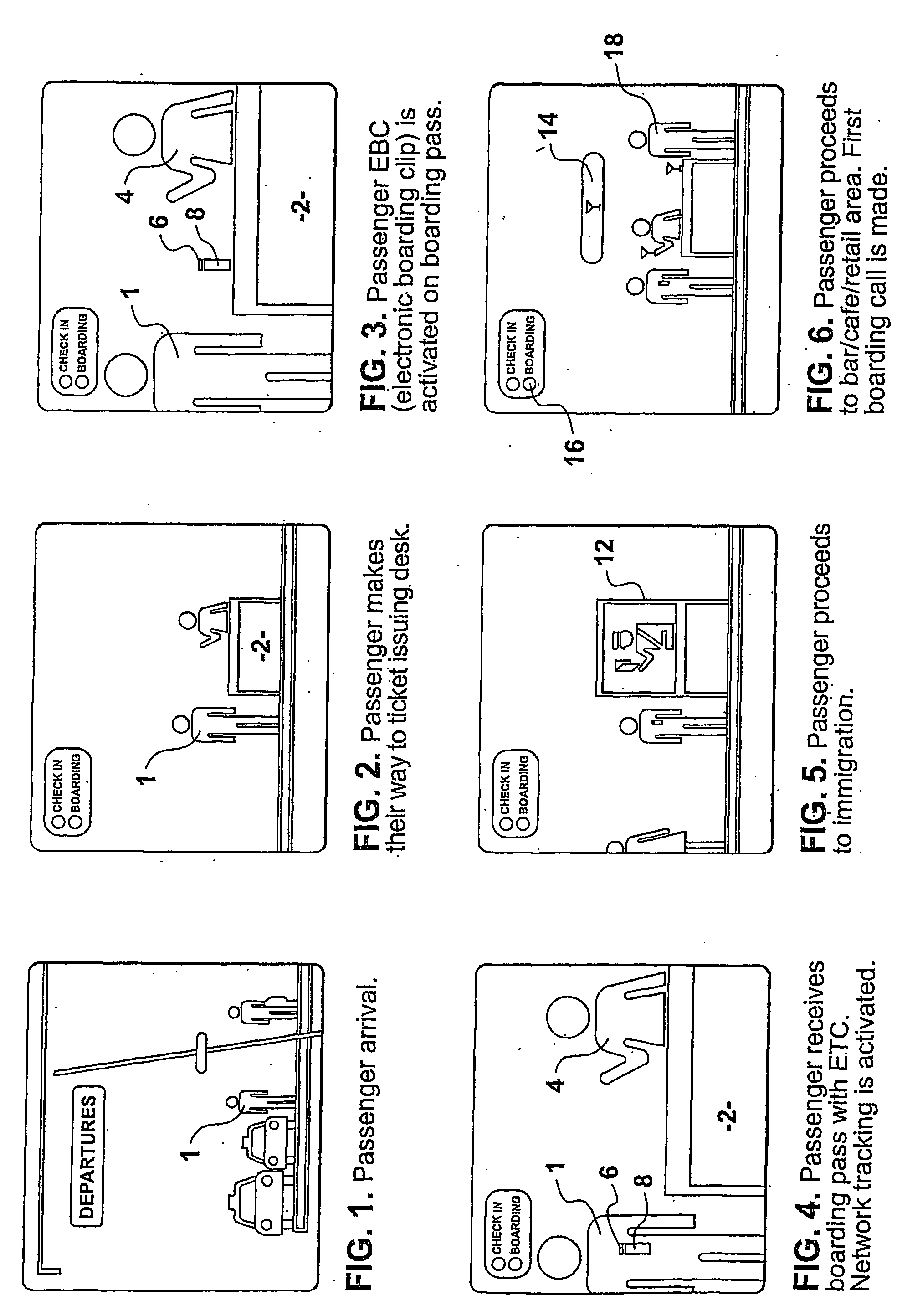
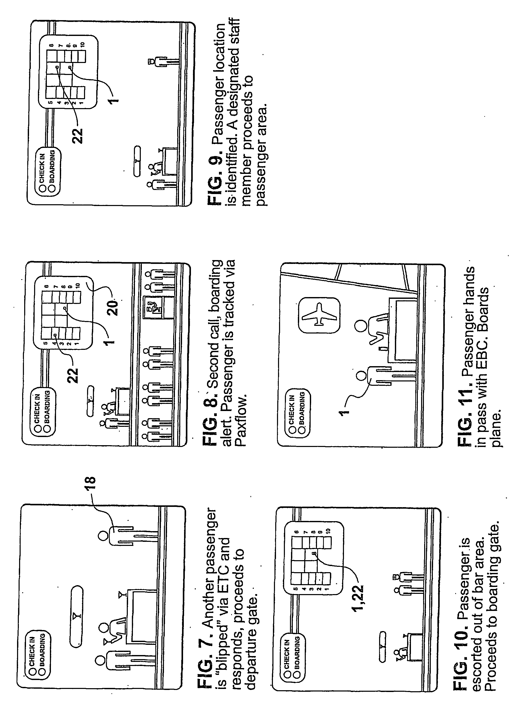
[0060] The most preferred embodiment described in this document refers to implementation of the invention in an airport environment. The invention and disclosure is not intended to be limited to this one application. The invention may be implemented in a number of other industries and environments. By way of example, some of these environments may include transportation terminals or stations (such as train stations, sea passage terminals, ferry terminals), hotels, casinos, shopping malls, entertainment complexes, factories, amusement parks, retail stores, service stations, banks, supermarkets and restaurants. Another field of application outside enclosed buildings or areas is vehicle tracking. This can be useful in relation to trucking companies, document tracking and courier or delivery services.

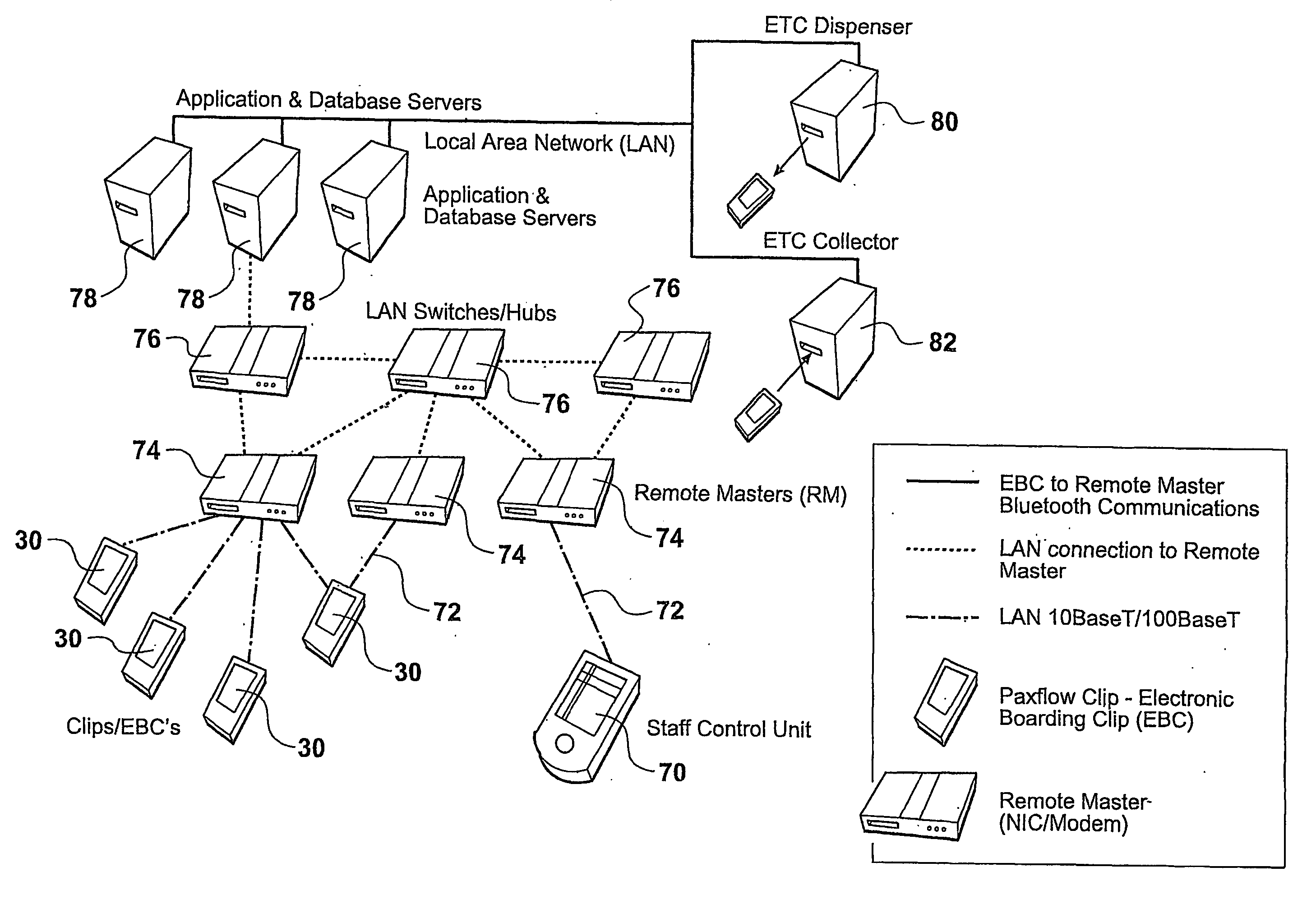
[0061] By way of a general overview, the system utilises a matrix of access points located at fixed locations throughout a nominated or defined space connected directly to a local area netw...


PUM


Abstract

A passenger location system comprises a plurality of radio transceivers at predtermined locations in a passenger terminal facility. At least one transponder is associated in use with a passenger. The transponder is adapted to transmit a radio signal in response to receiving a signal from one or more of the transceivers. The transponder signal is capable of being received by more that one tranceiver. The passenger location means is adapted to determine the position of the transponder by determining the location of the one or more transceiver that have received the transponder signal.

Description

[0001] This invention has relevance to communication systems and to location, tracking and identification systems. The invention is directed particularly, but not solely, toward location and tracking of, and communication with, individuals. The invention may also be used to track or locate inanimate objects.[0002] There are many industries in which it is desirable to track people or objects, for example, vehicles, baggage or documents, in real time. One particular industry is the air travel industry, where it is very desirable for economic and security reasons to be able to track passengers within airports. However, the travel industry generally also has a need for passenger location and tracking systems. Other environments where tracking and location is desirable include casinos, cruise ships, amusement facilities and hospitals. Location, tracking and communication in relation to medical alert systems and security systems is also desirable.[0003] In the case of air travel, it has l...

Claims


Application Information

Patent Timeline
IPC IPC(8): G01S13/75G01S13/87G01S13/91G01S19/14G07C9/00
CPCG01S13/75G01S13/878G08B13/2462G07C9/00111G07C2011/02G01S2013/916G07C9/28
Inventor LEA, KELVIN EDWARDLOWTHER, JONATHAN RAE
Owner PAXFLOW PATENTS
Features
  • Generate Ideas
  • Intellectual Property
  • Life Sciences
  • Materials
  • Tech Scout
  • Unparalleled Data Quality
  • Higher Quality Content
  • 60% Fewer Hallucinations
Learn More