
Transfer tape

a technology of transfer tape and adhesive film, which is applied in the direction of film/foil adhesives without carriers, film/foil adhesives, other domestic articles, etc., can solve the problems of adhesive film adhering to the dispenser itself, affecting the operation of the dispenser, and not being easy to cu

Inactive Publication Date: 2004-09-16
GENERAL CO LTD
View PDF11 Cites 9 Cited by
  • Summary
  • Abstract
  • Description
  • Claims
  • Application Information

AI Technical Summary

Problems solved by technology

But if this adhesive strength is too high, the adhesive film cannot be easily cut when one attempts to cut it at the desired location, but rather it is stretched out in strings between the side of the targeted object and the side of the band-shaped ribbon (this phenomenon shall hereinafter be referred to as "stringiness").
When this stringiness occurs, in the case that the terminus of the stringiness is present on the side of the targeted object, for example, dumpling-like lumps may occur when the terminuses of the stringiness are concentrated on the targeted object, or a step may occur in the state of adhesion between the targeted object and the adhering object, or gaps may occur so that good adhesion is not achieved.
Moreover, there is a risk of the adhesive film adhering to the dispenser itself and having deleterious effects on its operation.
However, even if these proposals suppress stringiness, the adhesive film can only be cut at the positions of the predetermined protrusions or to the units of a stipulated size, so it cannot be cut at the desired positions (of size or length).
In addition, there are problems in that this increases cost due to the- difficulty of manufacturing special band-shaped ribbon, and the need for facilities for coating the band-shaped ribbon with a coating cut into stipulated units.
However, in the ones containing filler proposed in the aforementioned JP-A 2001-240812, the filler is spherical so the effect of allowing the film of the adhesive film cannot be reliably obtained, so there is a problem in that the cutting effect may not be obtained depending on the film thickness.
In addition, there is also a problem in that, while the amount of filler can be easily increased or the thickness of the adhesive film can be easily made thinner, the adhesive strength conversely decreases.
In addition, with the adhesive transfer tape proposed in JP-B 6-62920, the membranous character of the adhesive film is weakened so it is easily cut, its adhesive strength may be extremely reduced due to inadequate dispersion of the alginic acid, or it may be cut at unnecessary locations, so the cutting effect cannot be reliably obtained over the entire adhesive film.
To wit, the conventional fillers had as their object to weaken (disrupt) the viscosity among the principal components of the adhesive film (membranous character of the adhesive film), and thereby lower the overall adhesive strength and simplify its cutting.
When the adhesive strength is increased, the viscosity among the adhesive components is high as described above, so a film that is not easily cut is formed.
But because it contains needle-shaped particles, when a force is applied in a direction other than the direction of the plane along which the band-shaped ribbon is coated with the adhesive film, the film of the adhesive film becomes thinner and then the needle-shaped particles rupture the film, thereby cutting the adhesive film.
If the maximum grain diameter of the needle-shaped particles is larger than 30 .mu.m and the particle length is longer than 500 .mu.m, then the tendency for the needle-shaped particles to become caught in the smoother of the gravure coater or the Meyer bar of the kiss coater, thereby causing streaks in the coating and deleteriously affecting the quality of coating becomes stronger.
The reason for this is that if it is thinner than 5 .mu.m, the transfer tape is susceptible to wrinkling or kinking which may cause malfunctioning.
On the other hand, if it is thicker than 60 .mu.m, then it is difficult to include longer lengths within the limited space within the transfer tool, the materials cost increases, and it may become resistant to bending, thus causing feed or transfer malfunctions.

Method used


Image

  • Transfer tape
  • Transfer tape
  • Transfer tape

Examples


Embodiment Construction

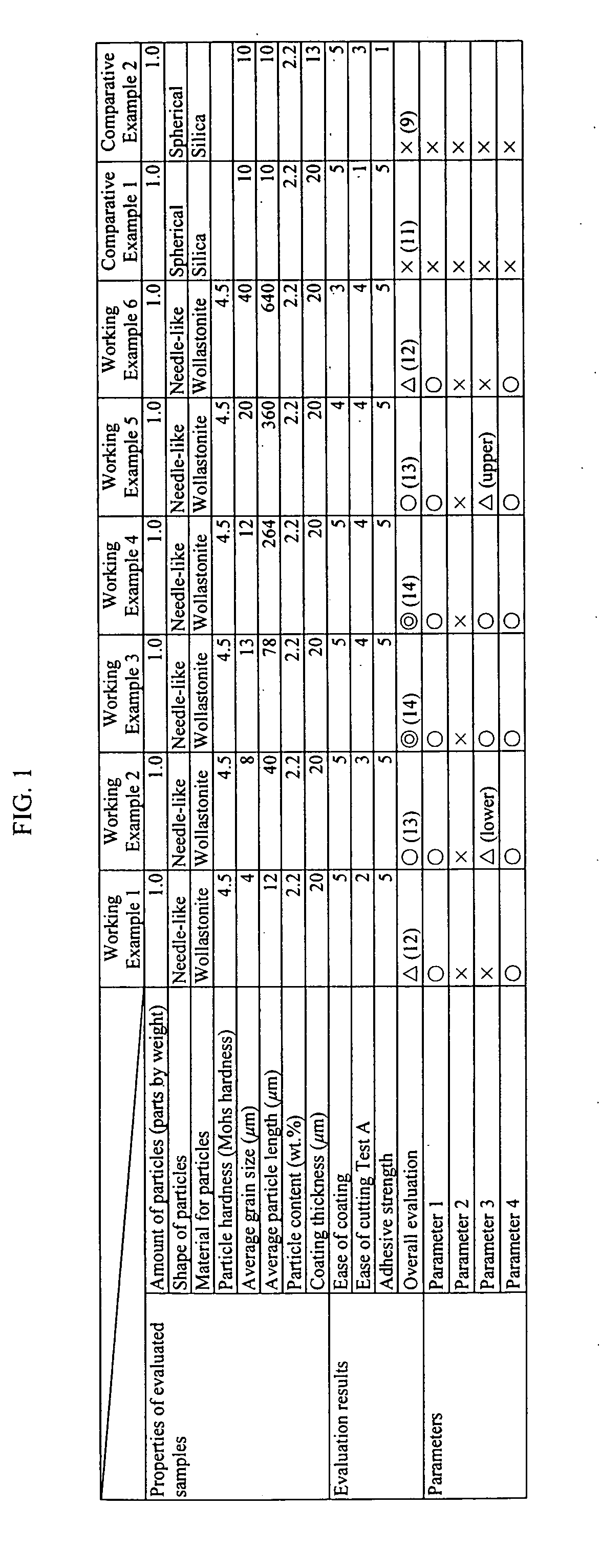
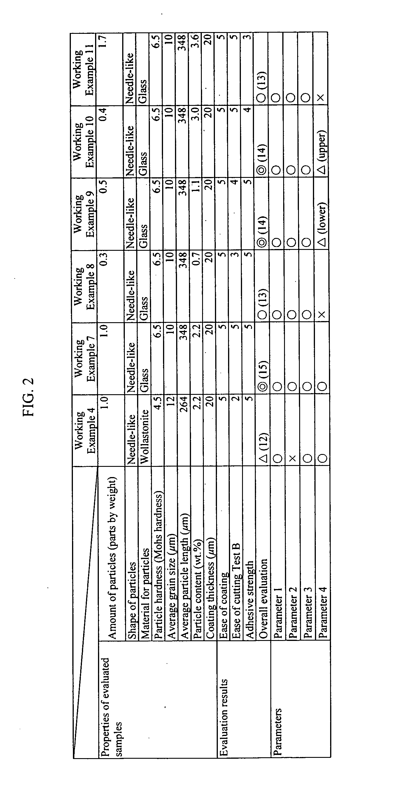
and Comparative Examples 1 and 2 adopt a uniform 1.0 parts by weight as the amount of needle-shaped particles and spherical particles. The values of the other parameters are presented in FIG. 1 and FIG. 2.

[0036] The adhesive coating used in the tests had the following composition:

[0037] Needle-shaped or spherical particles: 1.0 parts by weight (Working Examples 1-7 and Comparative Examples 1 and 2)

[0038] Emulsion-type acrylic adhesive: 37.0 parts by weight (parts by weight when converted to solids)

[0039] Rosin-based tackifier: 4.5 parts by weight (parts by weight when converted to solids)

[0040] Phthalocyanine Blue colorant: 1.5 parts by weight

[0041] Cissing preventative agent: 2.5 parts by weight

[0042] Water: 53.5 parts by weight

[0043] Note that in Working Examples 8-11, only the parts by weight of the needle-shaped or spherical particles was varied as illustrated in FIG. 2, while the other constituent ingredients were kept as the same parts by weight in the formula above.

[0044] Her...


PUM

PropertyMeasurementUnit
Fractionaaaaaaaaaa
Thicknessaaaaaaaaaa
Forceaaaaaaaaaa

Abstract

[An object of the present invention is] to provide transfer tape that maintains strong adhesive strength but can be reliably cut at a stipulated position. The adhesive film contains needle-shaped particles. If the adhesive strength is made high, then the adhesion between the adhesive ingredients is increased, thus forming a film that is difficult to cut. If a force is applied to the band-shaped ribbon in a direction outside the plane in which the adhesive coating is applied, then the film of the adhesive coating becomes thin and the needle-shaped particles rupture the film and cut the adhesive film. Moreover, the cut adhesive film draws the cut end to the needle-shaped particles, and as a result it is cut completely without stringiness.

Description

[0001] This application is a continuation application of International Application PCT / JP02 / 08848, that has an international filing date of Aug. 30, 2002, claiming priority under .sctn. 365(b) to Japanese Application 2001-305412 filed on Oct. 1, 2001. This continuation application fully incorporates the above applications by reference and further claims priority to the Japanese Application 2001-305412 filing date of Oct. 1, 2001 under .sctn. 119(a)-(d).[0002] 1. Technical Field[0003] The present invention relates to transfer tape that has an adhesive film formed by coating a band-shaped ribbon with an adhesive film transfers the adhesive film from the band-shaped ribbon to a targeted object, thereby adhering the targeted object to another adhering object by means of the adhesive film transferred to said targeted object, and more particularly to transfer tape that maintains strong adhesive strength but can be reliably cut at a stipulated position.[0004] 2. Technical Background[0005] ...

Claims


Application Information

Patent Timeline
IPC IPC(8): C09J7/10C09J11/00C09J11/04C09J201/00
CPCC09J7/00C09J11/04Y10T428/28Y10T428/2848Y10T428/2891Y10S428/914C09J7/10
Inventor YAMASHITA, MASARU
Owner GENERAL CO LTD
Learn More