Method and device for defining elastic deformations and interal angle of a gyratory compactor

Inactive Publication Date: 2004-09-23
PINE INSTR
View PDF28 Cites 1 Cited by
  • Summary
  • Abstract
  • Description
  • Claims
  • Application Information

AI Technical Summary

Benefits of technology

0008] The purpose of this invention is to provide a method and a device, which reduces or eliminates earlier mentioned problems connected with present methods of defining elastic deformations and internal angles of gyratory compactors. Especially, the purpose of the invention is to provide a method and a device, by use of which the elastic properties of a gyratory compactor fram

Problems solved by technology

A change in the angle of gyration is usually the most significant factor of error having influence on results in measuring compaction properties in gyratory compactor.
The situation is especially serious when the mass specimen is causing heavier loadings or variable loadings to the gyratory compactor (i.e. a "stiff" or coarse mixture).
This kind of studying of tests and their results is rather troublesome and slow.
Furthermore, measuring results gathered with this kind of method are inaccurate, among other things, because properties and density of mass specimen vary uncontrollably and relatively much, although the mass specimen has been taken from the same mass specimen source.
There are many disadvantages and imperfections connected to the measuring device of U.S. Pat. No. 6,477,

Method used


Image

  • Method and device for defining elastic deformations and interal angle of a gyratory compactor
  • Method and device for defining elastic deformations and interal angle of a gyratory compactor
  • Method and device for defining elastic deformations and interal angle of a gyratory compactor

Examples


Embodiment Construction

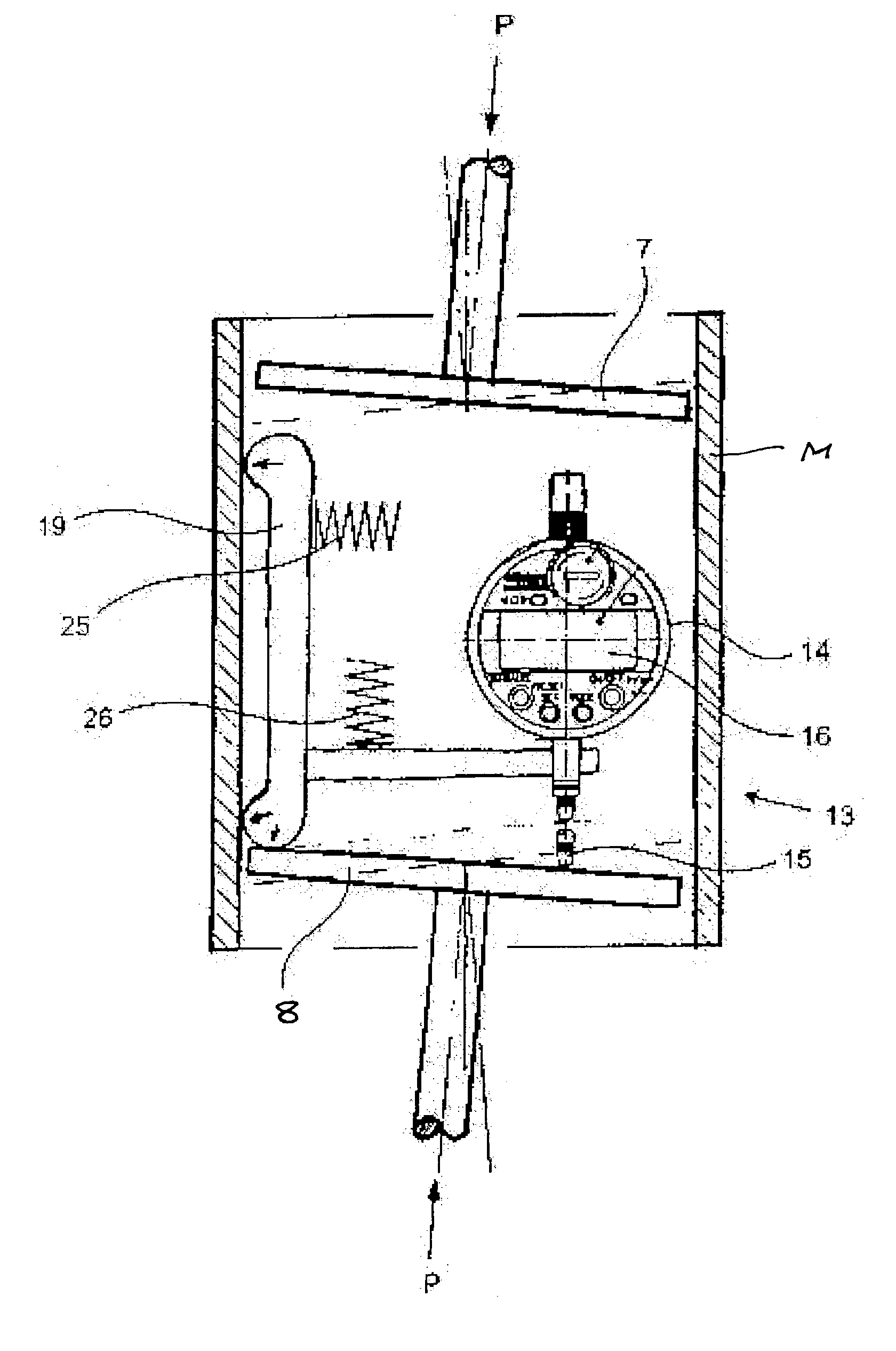
[0025] A device of the invention includes a loading device suitable to be placed into a specimen cylinder mold of a gyratory compactor as well as measuring elements for measuring the angle of gyration and a processing unit for measuring results to be connected to measuring elements for processing the measuring results of the angle of gyration and converting to elastic deformations of a gyratory compactor.

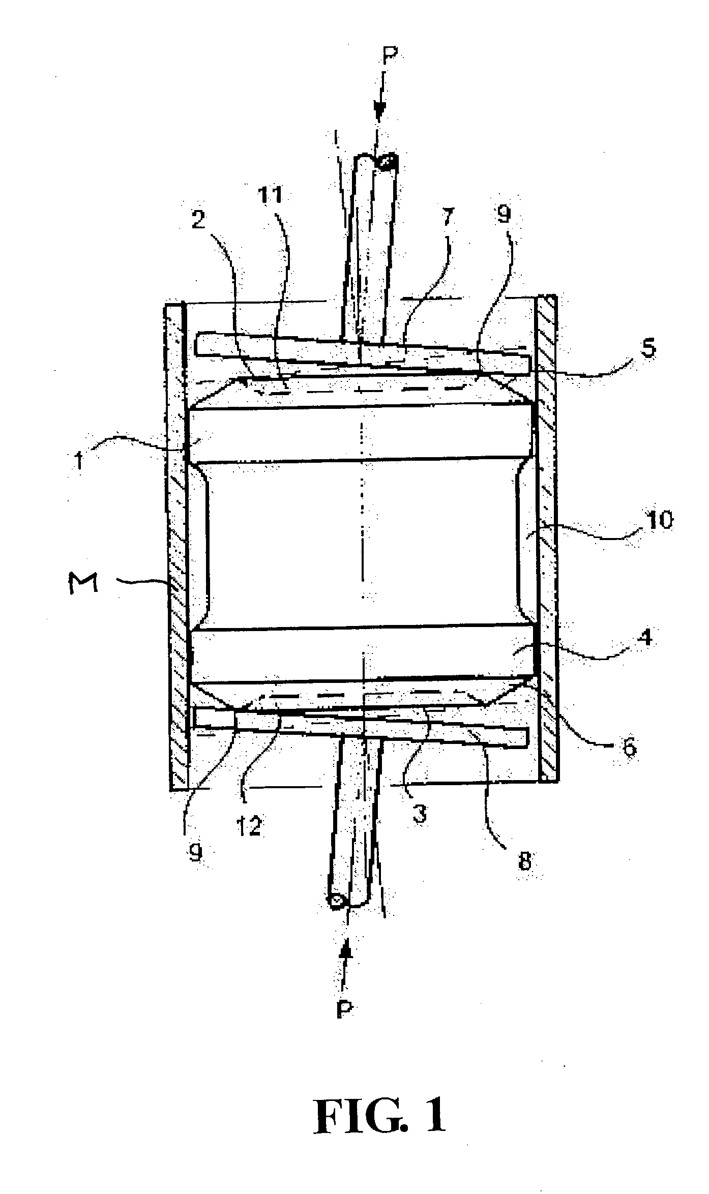
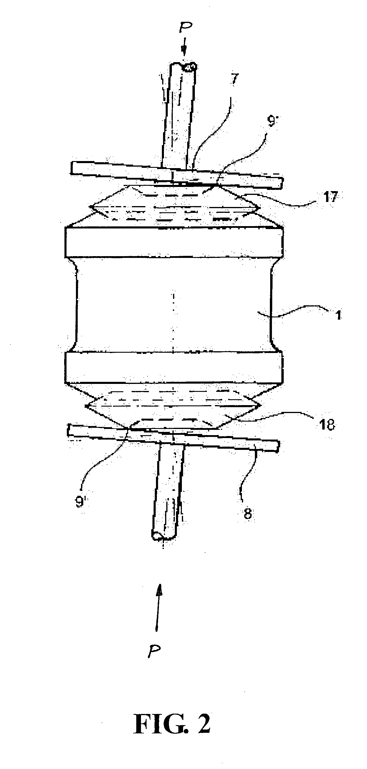
[0026] In FIG. 1 there is a loading device 1 placed into a specimen cylinder mold M of a gyratory compactor. The loading device in accordance with FIG. 1 has been made of suitable solid material, such as steel, aluminum or plastic, with a body in the shape of a cylinder with head surfaces 2 and 3, as well as casing surface 4 between the head surfaces. The head surfaces 2 and 3 extend or project from respective ends of the loading device body. The diameter of the loading device is such that it can be placed inside a standard size specimen cylinder mold of a gyratory compactor with cl...


PUM


Abstract

The object of the invention is a method for defining elastic deformations and integral angle between of the most important parts of a gyratory compactor, in which method the angle of gyration of a gyratory compactor is measured during the use of the gyratory compactor. The object of the invention is also a device in accordance with the claim 1, which device includes measuring elements (13, 20, 27, 28) for measuring the angle of gyration of a gyratory compactor. Characteristic to the method in accordance with the invention is the fact that a loading device (1) is adjusted in the place of mass specimen, the loading of which on the gyratory compactor is earlier known and that the gyratory compactor will be in use while the loading device (1) is inside the gyratory compactor. Characteristic to the device in accordance with the invention is the fact that the device includes at least one loading device which can be placed inside the specimen cylinder mold of the gyratory compactor.

Description

[0001] This application claims the benefit of Patent Application No. FI-20020560, filed in Finland on Mar. 22, 2002. This application claims the benefit of Patent Application No. FI-20022035, filed in Finland on Nov. 15, 2002.[0002] The present invention relates to a method for accurately inducing elastic deformations of a gyratory compactor, and measuring the internal angle of gyration. The internal angle of gyration is the angle formed between the axis of a cylindrical mold and the end plates of the mold.[0003] A gyratory compactor is used for defining properties of compaction of various masses of soil and similar substances, such as bituminous asphalt. For measurements the specimen mold of a gyratory compactor is filled with mass specimen. The specimen is compressed under vertical pressure and the so called gyratory movement, which causes shear strain across the specimen. These actions make the particles of the specimen to move in respect with each other finding their positions t...

Claims


Application Information

Patent Timeline
IPC IPC(8): G01M99/00G01B5/30G01N1/28G01N3/00G01N3/06G01N3/08G01N3/56
CPCG01N1/286G01N3/08G01N2203/0682G01N2203/0028G01N3/565
Inventor PAAKKINEN, ANTTI
Owner PINE INSTR
Why Eureka
Try Eureka