Reflective LCD, semitransmitting reflective LCD and electronic device

a reflective display and semi-transmitting technology, applied in non-linear optics, instruments, optics, etc., can solve the problems of difficult simultaneous increase of brightness and contrast ratio in reflective display, and great difficulty in precise color correction

Inactive Publication Date: 2004-09-23
BOE TECH GRP CO LTD
View PDF5 Cites 3 Cited by
  • Summary
  • Abstract
  • Description
  • Claims
  • Application Information

AI Technical Summary

Benefits of technology

[0013] In the reflective liquid crystal device in each of the first and second aspects of the present invention, external light incident on the polarizer side is reflected by the reflecting electrode layer provided on the first substrate through the polarizer, the transparent second substrate, and the liquid crystal, and is again emitted from the polarizer side through the liquid crystal, the second substrate and the polarizer. Therefore, the intensity of external light emitted as display light through the liquid crystal after reflection by the reflecting electrode layer can be controlled, for example, by controlling the orientation state of the liquid crystal using an electric field between the reflecting electrode layer (reflecting electrode) provided on the first substrate and the transparent electrode (counter electrode) provided on the second substrate. The presence of the transparent substrate between the liquid crystal and the reflector prevents the occurrence of double exposure and blurring of display, thereby permitting the achievement of sufficient coloring even in a color display. By using the two retardation plates including the first and second retardation plates arranged between the polarizer and the second substrate, color correction can easily and precisely be performed. The reflecting electrode layer means a single layer or multilayer film having both the reflecting function and the electrode function.
[0101] In the first embodiment shown in FIG. 2, each of the reflecting electrodes 14 comprises a single layer composed of Al as a main component, and thus reflectance can be improved by a relatively simple manufacturing process at relatively low cost. However, even when another metal such as Ag (silver), Cr (chromium) is used as the main component of the reflecting electrodes 14, the same effect as the above-described first embodiment can be obtained.

Problems solved by technology

However, in the reflective liquid crystal device disclosed in Japanese Unexamined Patent Application Publication No. 8-114799, it is very difficult to simultaneously increase brightness and the contrast ratio.
Particularly, in a color display, the use of one or a plurality of retardation plates (retardation film) for color correction has the problem of causing a great difficulty in precise color correction at the same time as increases in brightness and contrast ratio.
On the other hand, in the transflective liquid crystal device disclosed in Japanese Unexamined patent Application Publication No. 7-318929, it is very difficult to simultaneously increase brightness and the contrast ratio in a reflective display.
Particularly, in a color display, the use of one or a plurality of retardation plates (retardation film) for color correction has the problem of causing a great difficulty in precise color correction at the same time as increases in brightness and contrast ratio in a reflective display.
Although the applicant of this application proposes a novel transflective liquid crystal device in Japanese Patent Application No. 10-160866, this liquid crystal device has a problem in which particularly in a reflective display, a sufficient reflectance cannot be obtained to produce a dark display.

Method used


Image

  • Reflective LCD, semitransmitting reflective LCD and electronic device
  • Reflective LCD, semitransmitting reflective LCD and electronic device
  • Reflective LCD, semitransmitting reflective LCD and electronic device

Examples


first embodiment

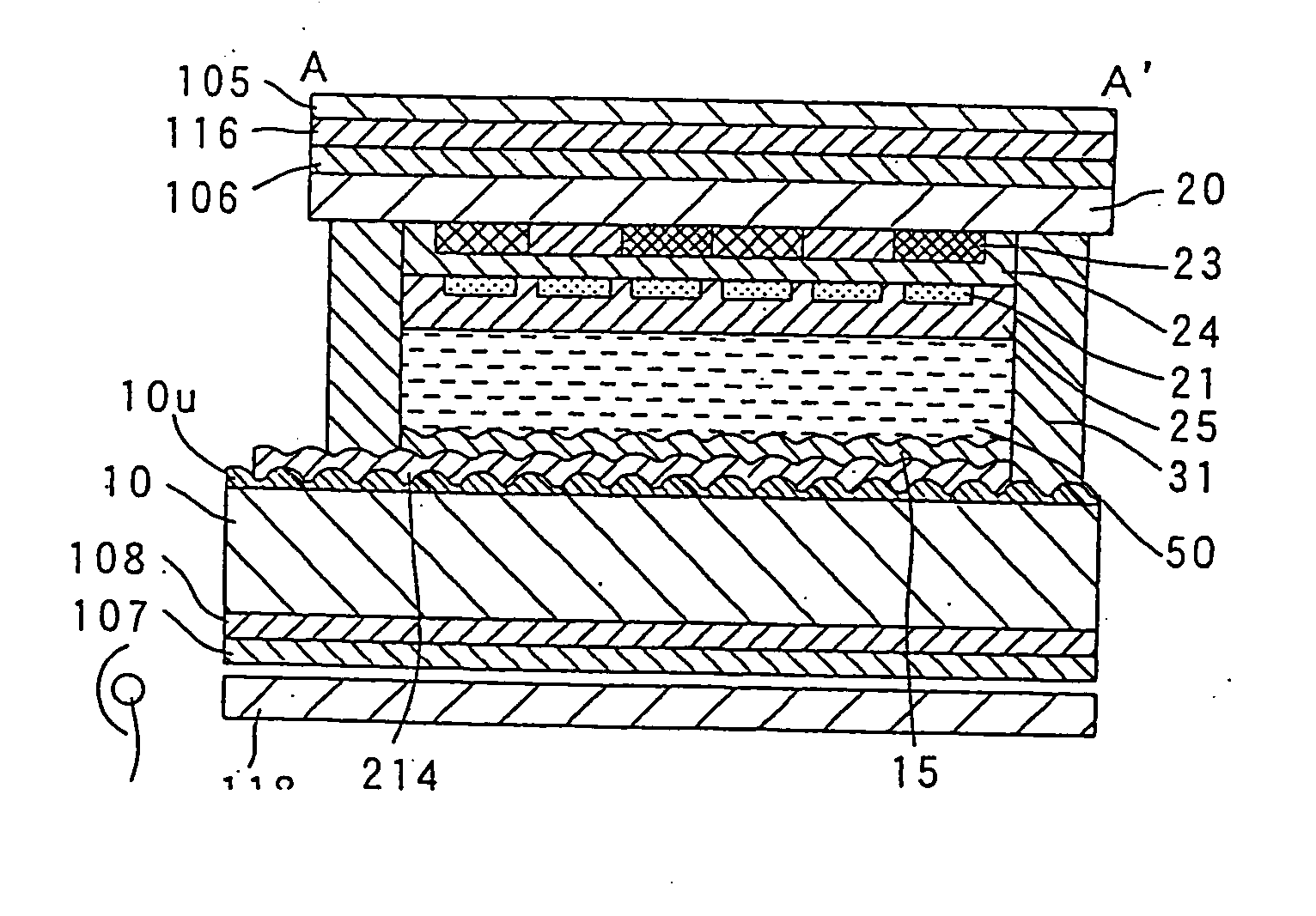
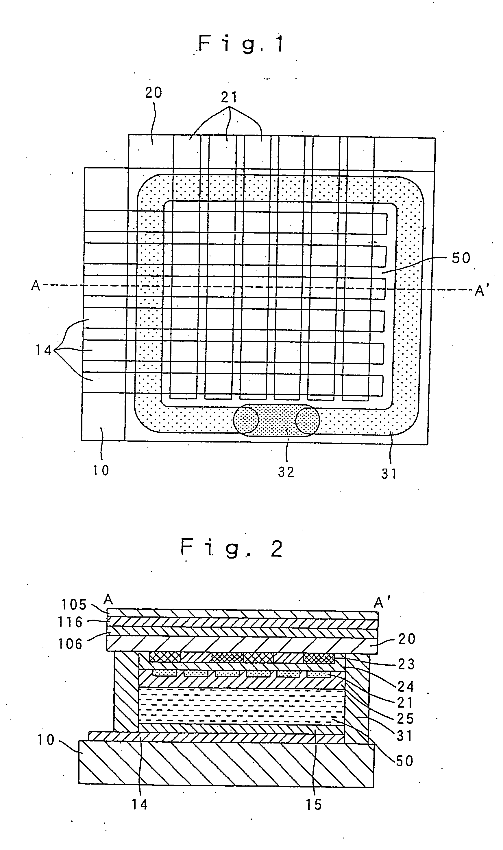
[0107] In various embodiments including this embodiment, each of the first retardation plate 106 and the second retardation plate 116 preferably comprises a biaxial retardation plate and satisfies the condition Nx>Nz>Ny (wherein Nx: refractive index in the X axis direction, Nz: refractive index in the Z axis direction, Ny: refractive index in the Y axis direction). This construction can widen the field of vision. However, even when each of the first retardation plate 106 and the second retardation plate 116 comprises a uniaxial retardation plate, the advantages of the first embodiment can be obtained.

second embodiment

[0108] (Second Embodiment)

[0109] A reflective liquid crystal device in accordance with a second embodiment of the present invention is described with reference to FIG. 7. The second embodiment of the present invention is different from the first embodiment in the parameter settings of the first retardation plate 106, the second retardation plate 116, and the polarizer 105, and the other components and operations are the same as the first embodiment shown in FIGS. 1 to 3.

[0110] Namely, like in the first embodiment, in the second embodiment, the twist angle .theta.t of the liquid crystal layer 50 comprising a STN liquid crystal is limited to 230 to 260 degrees, the minimum and maximum .DELTA.nd of the liquid crystal layer 50 are 0.85 .mu.m or less and 0.70 .mu.m or more, respectively.

[0111] Unlike in the first embodiment, in the second embodiment, .DELTA.nd of the first retardation plate 106 is 150.+-.50 nm, .DELTA.nd of the second retardation plate 116 is 610.+-.60 nm, the angle .the...

third embodiment

[0115] (Third Embodiment)

[0116] A reflective liquid crystal device in accordance with a third embodiment of the present invention is described with reference to FIG. 8. In the third embodiment shown in FIG. 8, the same components as the first embodiment shown in FIGS. 1 to 3 are denoted by the same reference numerals as the first embodiment, and description thereof is omitted.

[0117] The third embodiment is different from the first or second embodiment in that unevenness is formed on the surface of the first substrate 10 to accordingly form unevenness on the reflecting electrodes 14 and the alignment film 15, and the thickness d of the liquid crystal layer 50 in each pixel slightly changes with position. The other components of the third embodiment are the same as the first or second embodiment.

[0118] Therefore, the third embodiment comprises a first substrate 10' having an uneven surface so that each of the reflecting electrodes 14 has an uneven surface facing the liquid crystal lay...


PUM

PropertyMeasurementUnit
twist angleaaaaaaaaaa
thicknessaaaaaaaaaa
thicknessaaaaaaaaaa

Abstract

A reflective liquid crystal device includes a reflecting electrode (14) provided on the liquid crystal side of a first substrate (10), and a first retardation plate (106), a second retardation plate (116) and a polarizer (105), which are provided on the side of a second substrate (20), which is opposite to the liquid crystal side thereof. The twist angle and Deltand of the liquid crystal are 230 to 260 degrees and 0.70 mum to 0.85 mum, respectively. Deltand of the first retardation plate is 150±50 nm, and Deltand of the second retardation plate is 610±60 nm. The angle formed by the transmission axis or absorption axis of the polarizer and the optical axis of the second retardation plate is 10 to 35 degrees, and the angle formed by the optical axis of the first retardation plate and the optical axis of the second retardation plate is 30 to 60 degrees. As a result, a bright image display having high contrast can be obtained.

Description

[0001] This application is a divisional application of U.S. Ser. No. 09 / 869,719 filed Jun. 29, 2001 which is a 371 application of International Application PCT / JP00 / 07770 filed Nov. 2, 2000 claiming priority to Japanese patent application Nos. 11-312933 filed Nov. 2, 1999 and 2000-000933 filed Jan. 6, 2000 all of which are incorporated by reference herewith.[0002] The present invention relates to a passive matrix driving system liquid crystal device or the like, and an electronic apparatus using the same. Particularly, the present invention relates to an internal reflection system reflective liquid crystal device and transflective liquid crystal device respectively comprising a reflecting layer and a transflective layer provided on the liquid crystal side of a substrate, and an electronic apparatus using such a liquid crystal device.[0003] A reflective liquid crystal device utilizing external light for display without using a light source such as a back light is conventionally advan...

Claims


Application Information

Patent Timeline
Patent Type & Authority Applications(United States)
IPC IPC(8): G02F1/1335G02F1/13363G02F1/139
CPCG02F1/133504G02F1/133553G02F1/133555G02F1/13363G02F2413/12G02F2202/40G02F2203/02G02F2413/03G02F2413/08G02F1/1397G02F1/1335
Inventor IIJIMA, CHIYOAKI
Owner BOE TECH GRP CO LTD
Why Eureka
Try Eureka