Exhaust gas cleaning system of internal combustion engine

Active Publication Date: 2004-09-30
DENSO CORP
View PDF5 Cites 63 Cited by
  • Summary
  • Abstract
  • Description
  • Claims
  • Application Information

AI Technical Summary

Problems solved by technology

However, such temperature increasing methods deteriorate fuel consumption.
However, if the DPF temperature T is too high, there is a possibility of damage to the DPF, degradation of an oxidation catalyst supported by the DPF or t

Method used


Image

  • Exhaust gas cleaning system of internal combustion engine
  • Exhaust gas cleaning system of internal combustion engine
  • Exhaust gas cleaning system of internal combustion engine

Examples


first embodiment

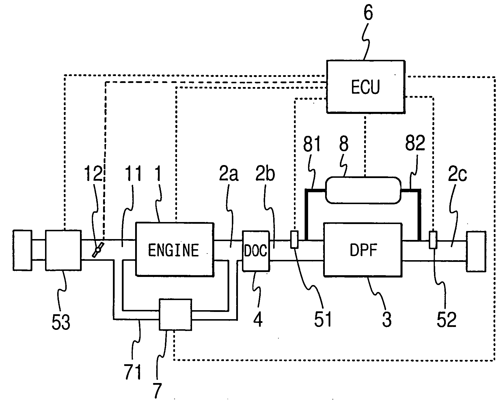
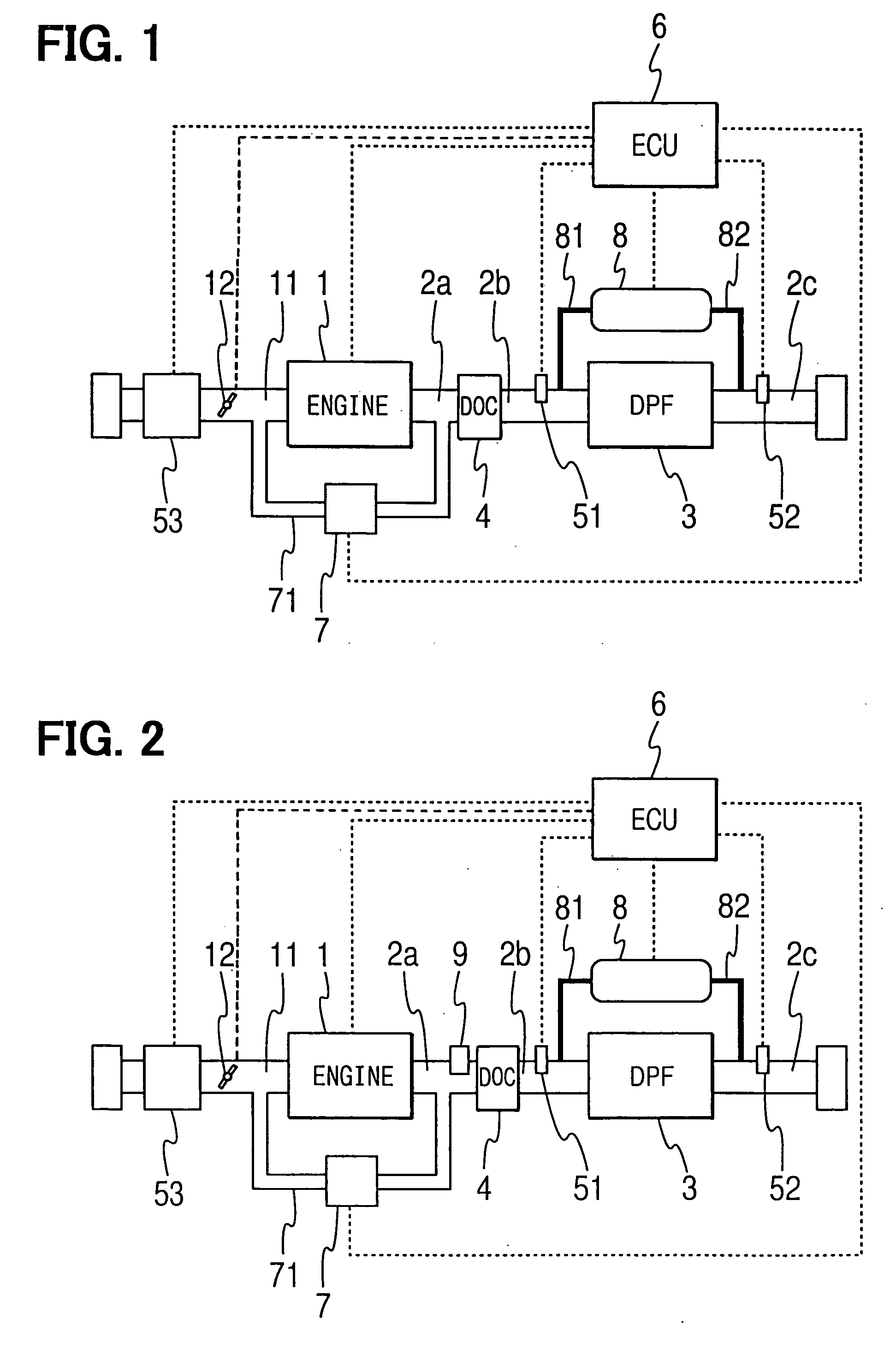
[0033] Referring to FIG. 1, an exhaust gas cleaning system of a diesel engine 1 according to a first embodiment of the present invention is illustrated. As shown in FIG. 1, a diesel particulate filter (a DPF) 3 is disposed between exhaust pipes 2b, 2c, which form an exhaust passage 2 of the diesel engine 1. An oxidation catalyst (a diesel oxidation catalyst: a DOC) 4 is disposed upstream of the DPF 3, between exhaust pipes 2a, 2b. The DPF 3 is a ceramic filter having publicly known structure. For instance, the DPF 3 is formed of heat-resistant ceramic such as cordierite in the shape of honeycomb structure having a multiplicity of cells as gas passages provided by separation walls. An inlet or an outlet of each cell is blocked alternately. The exhaust gas discharged from the engine 1 flows downstream while passing through the porous separation walls of the DPF 3. At that time, particulate matters are collected and accumulated in the DPF 3 gradually.

[0034] The DOC 4 has publicly known...

second embodiment

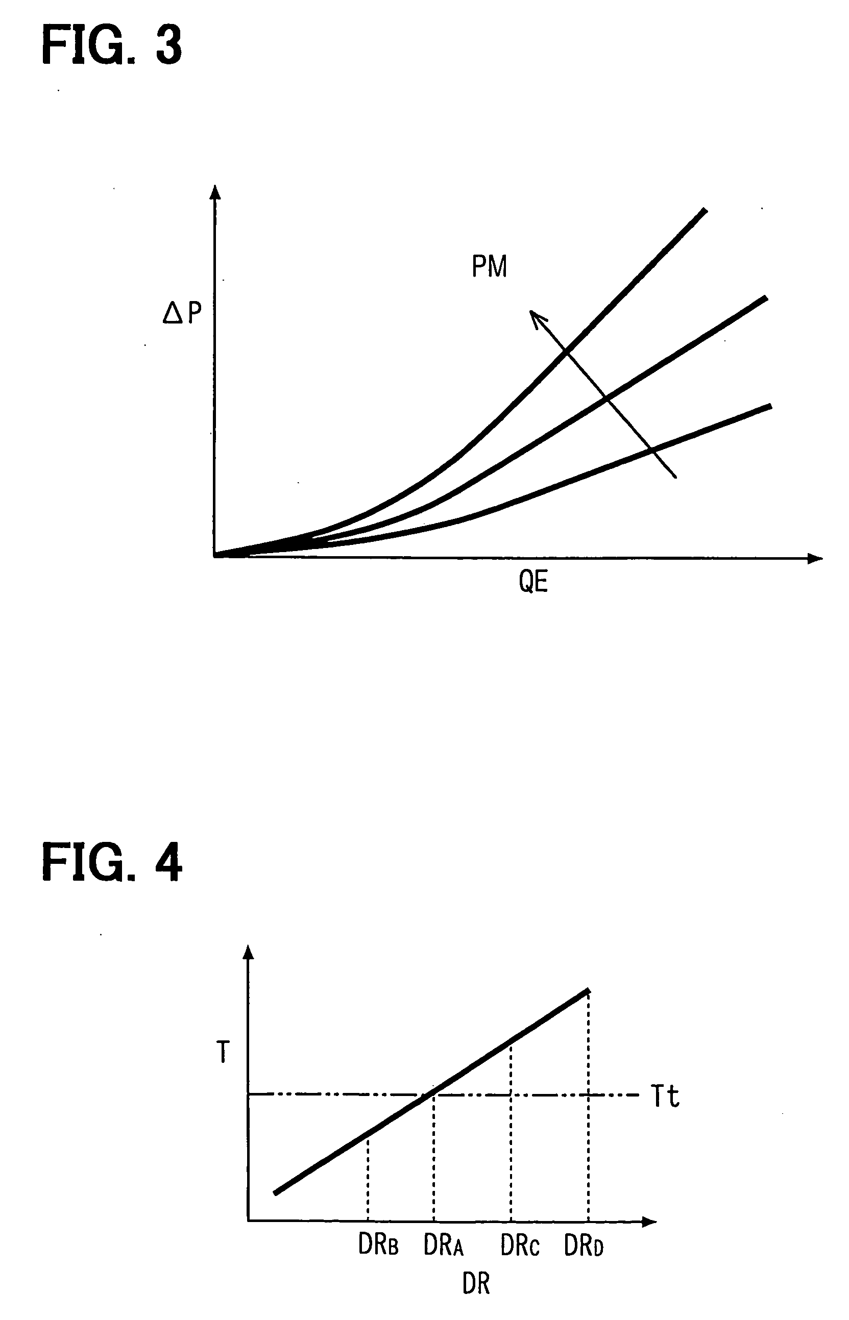
[0058] Next, regeneration control performed by an ECU 6 according to a second embodiment of the present invention will be explained based on FIG. 12. In the second embodiment, the duty ratio DR is changed continuously in accordance with the DPF temperature T. First, in Step S201, the ECU 6 receives the exhaust gas temperatures T1, T2 from the exhaust gas temperature sensors 51, 52, which are disposed upstream and downstream of the DPF 3 respectively. In Step S202, the DPF temperature T is calculated based on the exhaust gas temperatures. T1, T2. The temperature T1 or the temperature T2 may be simply employed as the DPF temperature T. Alternatively, the DPF temperature T may be calculated from the temperatures T1, T2. In Step S203, the particulate matter accumulation quantity PM of the DPF 3 is estimated. For instance, the particulate matter accumulation quantity PM is estimated from the pressure difference .DELTA.P across the DPF 3 sensed by the pressure difference sensor 8 and the ...


PUM


Abstract

An exhaust gas cleaning system of a diesel engine includes a diesel particulate filter (a DPF) disposed in an exhaust passage, and a diesel oxidation catalyst (a DOC) disposed upstream of the DPF. When an electronic control unit (an ECU) performs a temperature increasing operation such as post-injection to eliminate particulate matters accumulated in the DPF, a ratio (a duty ratio) between a performing period and an interrupting period of the temperature increasing operation is changed in accordance with temperature of the DPF. Thus, a quantity of hydrocarbon supplied to the DOC is controlled stepwise or continuously. Thus, the temperature of the DPF can be increased to target temperature quickly and can be maintained near the target temperature when the regeneration of the DPF is performed.

Description

[0001] This application is based on and incorporates herein by reference Japanese Patent Application No. 2003-94851 filed on Mar. 31, 2003.[0002] 1. Field of the Invention[0003] The present invention relates to an exhaust gas cleaning system of an internal combustion engine having a particulate filter in an exhaust passage. Specifically, the present invention relates to an exhaust gas cleaning system capable of performing temperature increase regeneration of a particulate filter.[0004] 2. Description of Related Art[0005] In recent years, an exhaust gas cleaning system, which reduces discharge of toxic components by treating exhaust gas discharged from an internal combustion engine with a catalyst or a filter, has gained importance as a measure to conserve the environment. For instance, an exhaust gas cleaning system having a diesel particulate filter (DPF) disposed in an exhaust pipe for collecting particulate matters discharged from the diesel engine is known. The DPF is regenerate...

Claims


Application Information

Patent Timeline
IPC IPC(8): F01N3/02F01N3/023F01N3/025F02D45/00F01N3/029F01N3/035F01N9/00F01N13/02F02D13/02F02D41/02F02D41/04F02D41/38F02D41/40
CPCF01N3/023F01N3/035F01N9/002F02D41/025F02D41/029F01N13/009F02D2200/0804F02D2200/0812Y02T10/44Y02T10/26Y02T10/47F02D41/405Y02T10/12Y02T10/40
Inventor OKUGAWA, SHINICHIROKUBOSHIMA, TSUKASA
Owner DENSO CORP
Why Eureka
Try Eureka