Light fixture cover system and method

a technology for lighting fixtures and cover systems, applied in outdoor lighting, lighting and heating equipment, lighting support devices, etc., can solve the problems of inability to secure the entire fixture cover, loss of security of the screw, loss of security of the cover, etc., to achieve convenient removal, resist bending, and permit effective heat transfer

Inactive Publication Date: 2004-10-14
WEBER MARTIN THOMAS
View PDF47 Cites 21 Cited by
  • Summary
  • Abstract
  • Description
  • Claims
  • Application Information

AI Technical Summary

Benefits of technology

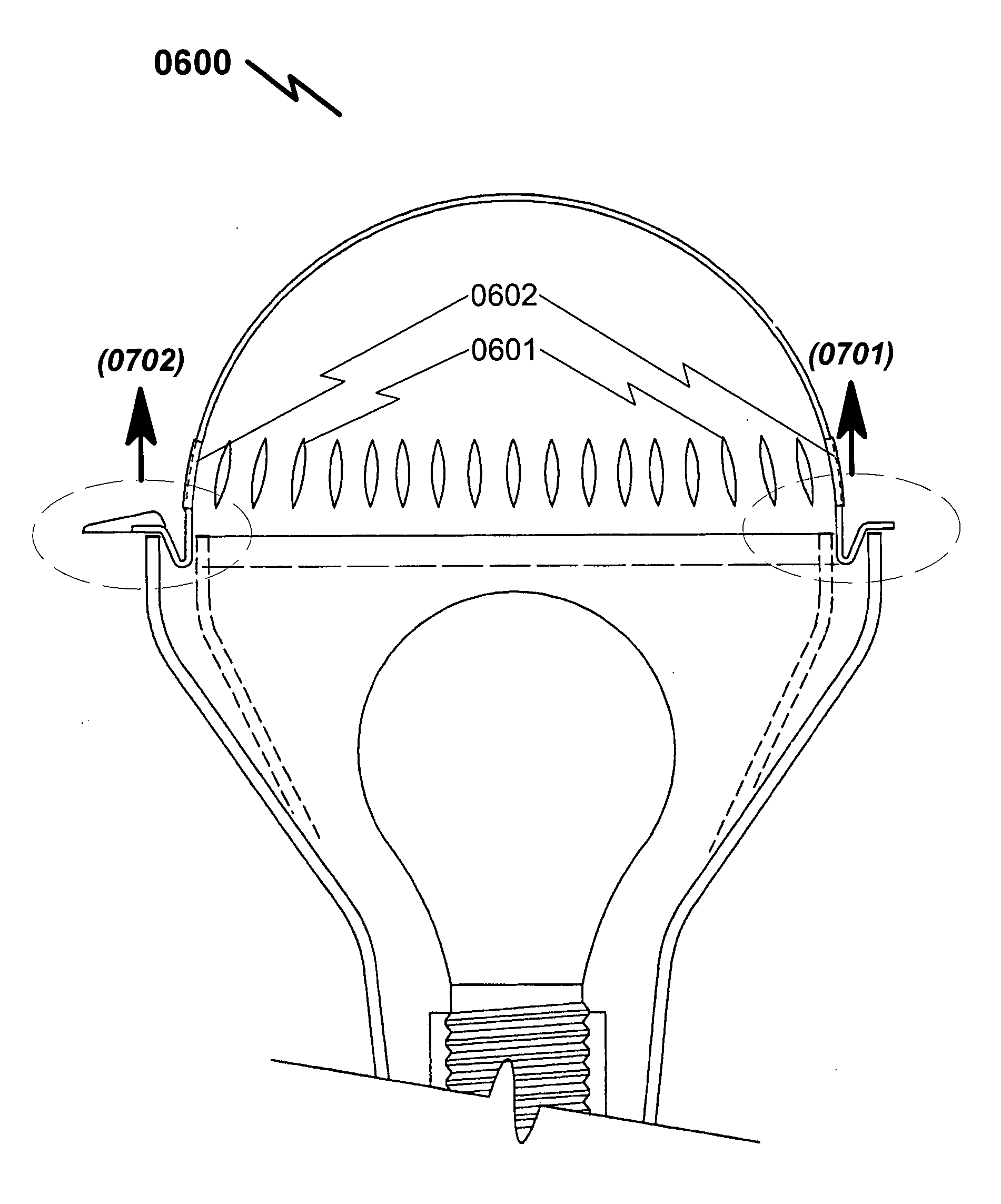
0039] (6) Still another object of the present invention is to provide a light fixture cover including a structurally reinforced tab that makes the cover readily removable.
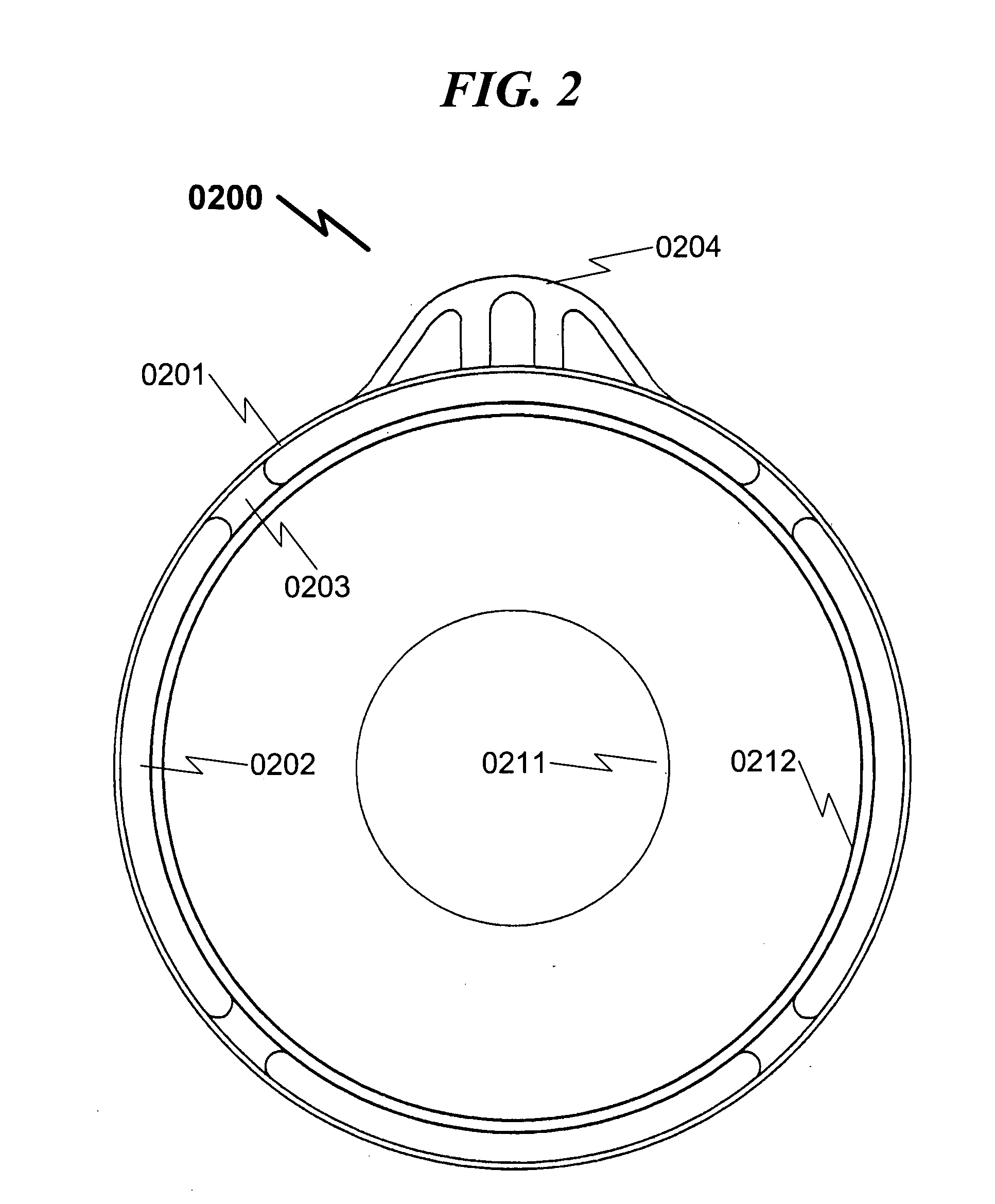
0040] (7) Yet another object of the present invention is to provide a flared tab member that attaches to a relatively large portion of the light fixture cover's external surface thereby spreading the separation force over a wide range of the sealing area adjacent to the tab.
0041] (8) Still another object of t

Problems solved by technology

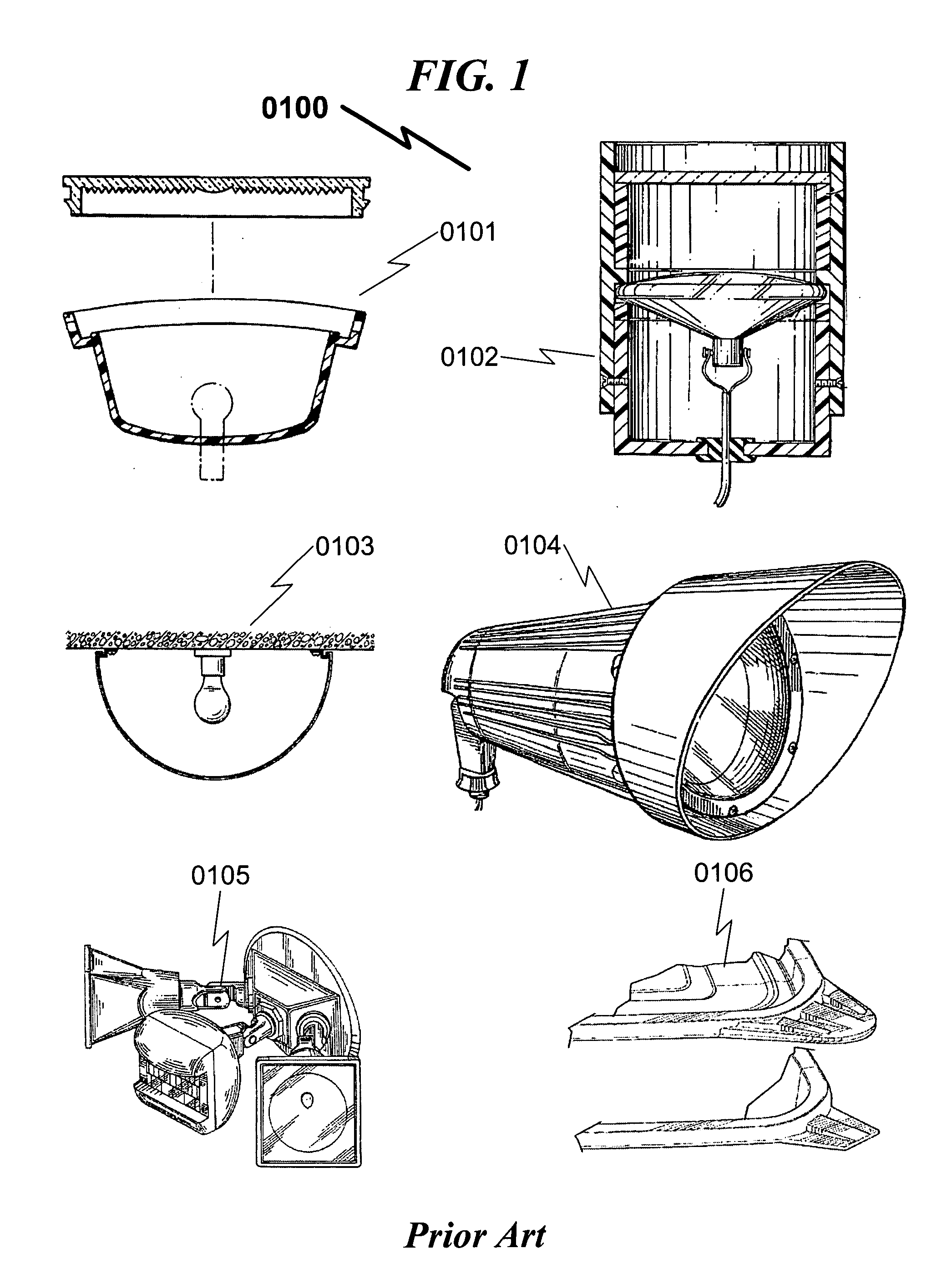
Also, it is awkward to remove and reattach the cover from an overhead fixture, while trying to access the screws from around the sides of the fixture, which often has a larger diameter than its base.
A fixture using only three screws for securing the fixture cover results in the inability to secure the entire fixture cover when a single screw is lost, which can easily occur.
The outwardly extending lip of such fixture covers invites misalignment, with the screw perhaps passing over, or into the edge of, the lip, again resulting in the loss of security by that screw and inability to secure the cover.
However, to the knowledge of the present inventor, no one has developed a selectively detachable cover that is also a unitary structure including a body having a peripheral sealing lip to secure a light fixture cover to its corresponding light fixture.
Additionally, no one has developed a cover with a removing tab and a waterproof surface in this economic range.
While the side of the fixture cover is a

Method used


Image

  • Light fixture cover system and method
  • Light fixture cover system and method
  • Light fixture cover system and method

Examples


Embodiment Construction

[0058] While this invention is susceptible of embodiment in many different forms, there is shown in the drawings and will herein be described in detailed preferred embodiment of the invention with the understanding that the present disclosure is to be considered as an exemplification of the principles of the invention and is not intended to limit the broad aspect of the invention to the embodiment illustrated.

[0059] The numerous innovative teachings of the present application will be described with particular reference to the presently preferred embodiment, wherein these innovative teachings are advantageously applied to the particular problems of a LIGHT FIXTURE COVER SYSTEM AND METHOD. However, it should be understood that this embodiment is only one example of the many advantageous uses of the innovative teachings herein. In general, statements made in the specification of the present application do not necessarily limit any of the various claimed inventions. Moreover, some state...


PUM


Abstract

A light fixture cover system and method is disclosed in which the selectively detachable cover is also a unitary structure including a body having a peripheral sealing lip that fits over any corresponding industry standard outside light fixture. From the outset, it should be noted that while the cover is illustrated generally as being of a round configuration, the cover may be of various other configurations such as rectangular, oval or square by way of non-limiting examples to fit all shapes of exterior light fixtures. The sealing lip of the cover has at least one laterally extending tab member to assist in removing the cover from the fixture. The cover portion is preferably made from a resilient polymeric material suitable for both winter and summer weather conditions in addition to being impervious to the heat generated by the electrical bulb or bulbs contained it the light fixture. Preferred embodiments of the present cover provide a tight fit between the cover and fixture base, thus precluding entry of insects or water into the interior of the assembly. The cover is devoid of screws, clips, or any other components, and requires no tools or other equipment to install and remove the light cover to and from its corresponding light fixture base.

Description

[0001] Applicant claims benefit pursuant to 35 U.S.C. .sctn. 119 and hereby incorporates by reference Provisional Patent Application for "LIGHT FIXTURE COVER SYSTEM AND METHOD", Ser. No. 60 / 462,006, docket MTW-2003-001, filed Apr. 11, 2003, and submitted to the USPTO with Express Mail on Apr. 11, 2003 with tracking number EU828406878US.PARTIAL WAIVER OF COPYRIGHT[0002] All of the material in this patent application is subject to copyright protection under the copyright laws of the United States and of other countries. As of the first effective filing date of the present application, this material is protected as unpublished material.[0003] However, permission to copy this material is hereby granted to the extent that the copyright owner has no objection to the facsimile reproduction by anyone of the patent documentation or patent disclosure, as it appears in the United States Patent and Trademark Office patent file or records, but otherwise reserves all copyright rights whatsoever.[...

Claims


Application Information

Patent Timeline
IPC IPC(8): F21V3/04F21V9/08F21V17/16F21V29/00F21V31/03
CPCF21V3/04F21V9/08F21V17/164F21V29/004F21V29/83F21W2131/10F21V3/02F21V29/506F21V31/03
Inventor WEBER, MARTIN THOMAS
Owner WEBER MARTIN THOMAS
Why Eureka
Try Eureka