
Display method, display controller, and display apparatus

a display device and display controller technology, applied in bridge materials, instruments, constructions, etc., can solve the problems of unbalanced video signal and light-emitting amount of light source, failure to display, and incomplete time-dependent step of displaying an adjusted video signal on a display device, so as to achieve the effect of improving display quality

Active Publication Date: 2004-10-21
PANASONIC CORP
View PDF25 Cites 48 Cited by
  • Summary
  • Abstract
  • Description
  • Claims
  • Application Information

AI Technical Summary

Benefits of technology

[0007] In view of the above, an object of the present invention is to provide a display method operable to provide improved display quality, and an art related thereto.

Problems solved by technology

However, according to the prior art, a step of displaying an adjusted video signal on a display device is entirely unassociated in terms of time with a step of switching a light source to a value at which the luminance of the light source has been regulated.
As a result, despite an earnest effort to closely adjust the video signal to be applied to the display device, the video signal is often unbalanced with a light-emitting amount of the light source.
More specifically, the prior art sometimes results in unsuccessful display such as an obscure image plane and a conspicuous change between brighter and darker light sources.

Method used


Image

  • Display method, display controller, and display apparatus
  • Display method, display controller, and display apparatus
  • Display method, display controller, and display apparatus

Examples


example no.2

EXAMPLE NO. 2

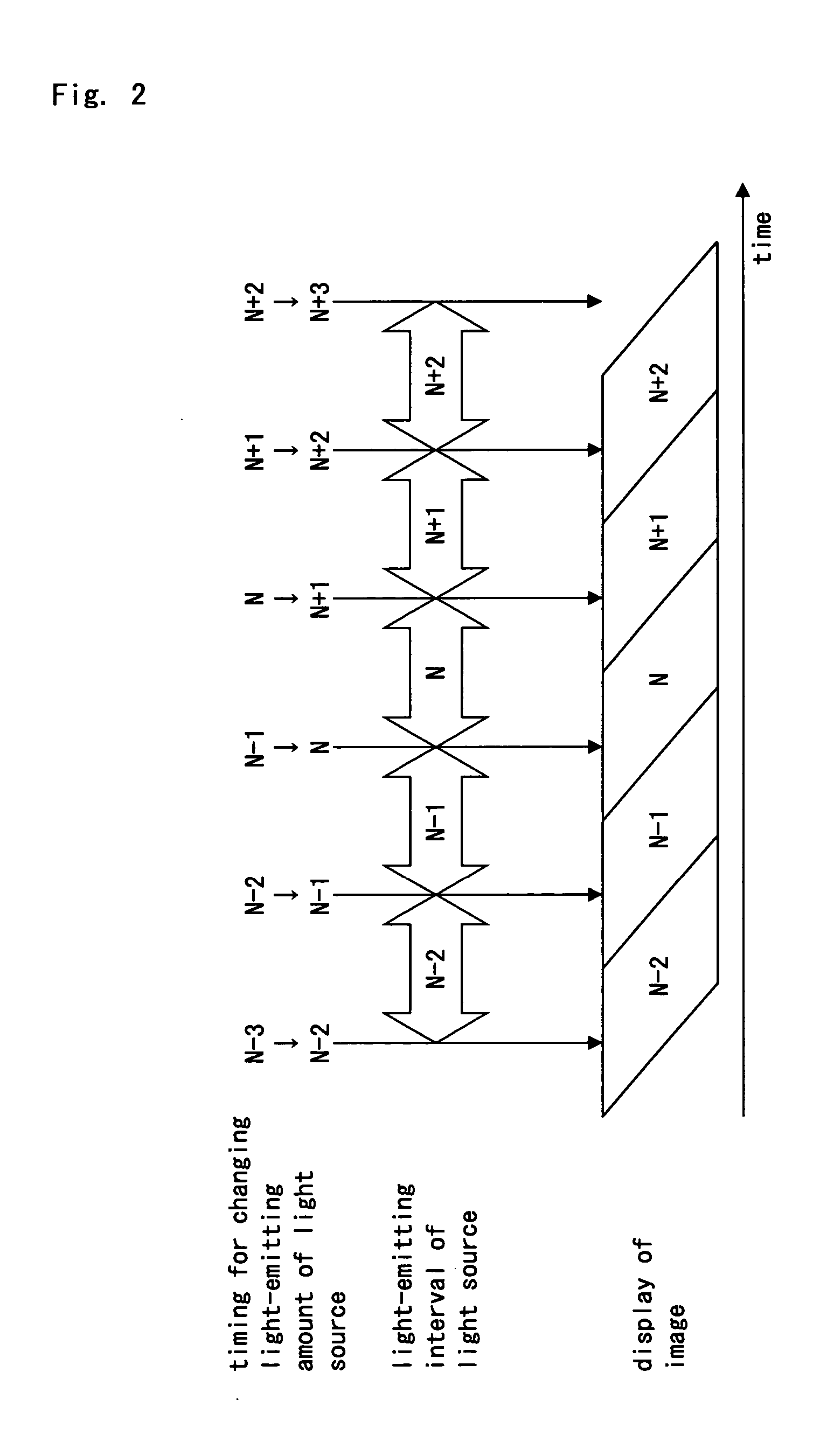
[0063] Example No. 2 is now described with reference to FIG. 5. The present example as illustrated in FIG. 5 presupposes that the light source 104 has a response speed of 1 ms or greater (e.g., 4 ms).

[0064] As illustrated in FIG. 5, the video signal-analyzing unit 100 controls the video signal-adjusting unit 101 and the light source-controlling unit 102 in such a manner that the moment when a response from the light source 104 reaches a halfway of a target is consistent with the moment when the image plane on the display device 103 reaches a half of renewal. The half of the renewal of the image plane refers to an exactly intermediate point between the moment when an "N"-frame starts being replaced by a "N+1" frame and the moment the replacement ends.

[0065] Example No. 1 or 2 maintains an invariably appropriate relationship between the Vsync-signal, the transfer of the video signal to the display device 103, a response speed of the liquid crystal, a response speed of the...


PUM


Abstract

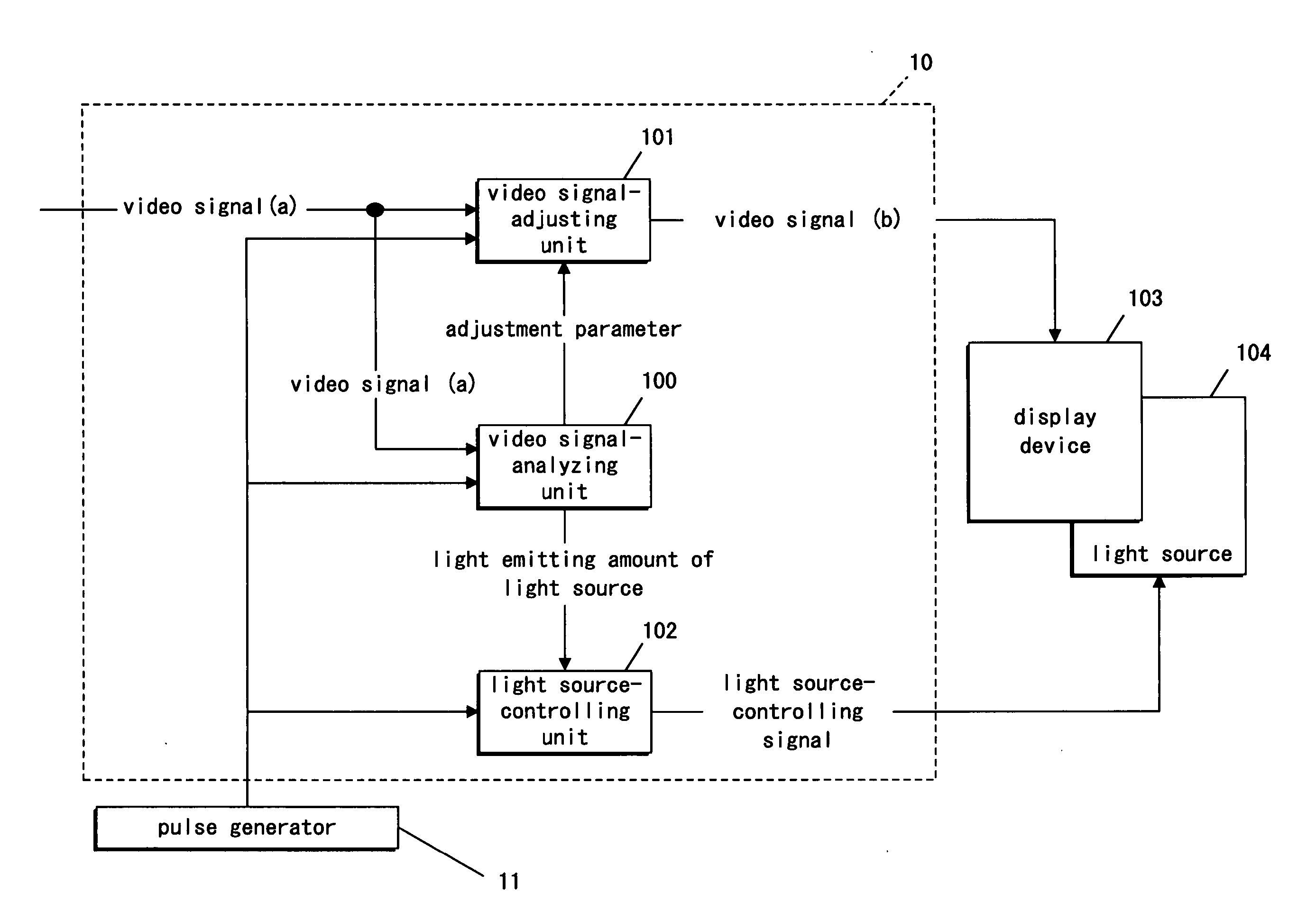
A display controller including a video signal-analyzing unit, a video signal-adjusting unit operable to receive a video signal, to adjust the video signal in accordance with adjustment parameter information, and to feed the adjusted video signal into a display device, and a light source-controlling unit operable to feed a light source-controlling signal into a light source in accordance with light source light-emitting amount information. The video signal-analyzing unit allows timing in which the display device displays a picture in accordance with the adjusted video signal from the video signal-adjusting unit to be synchronized with timing in which the light source changes a light-emitting amount in response to the light source-controlling signal from the light source-controlling unit. As a result, such two different timings are held in a proper relationship with one another, and degradation in image quality is suppressed, which otherwise would result from a change in the light source to become dark and bright. This feature realizes high-quality video display.

Description

[0001] 1. Field of the Invention[0002] The present invention relates to a display method, a display controller, and a display apparatus. In particular, it relates to an art of dynamically adjusting a video signal and light source luminance in accordance with entered video data in a video-displaying apparatus that is operable to display a picture by illuminating, with light from a light source, a light-receiving display device as represented by a liquid crystal panel.[0003] 2. Description of the Related Art[0004] In order to provide a light source with less power consumption and a longer life display device, a video signal-adjusting value and a light source luminance-regulating value have been controlled in a manner correlated therebetween in response to an entered video signal, a photosensor, and a temperature sensor, thereby realizing a power saving and a longer lifetime in the display device. Such a prior art is disclosed in published Japanese Patent Application Laid-Open No. 5-66...

Claims


Application Information

Patent Timeline
IPC IPC(8): G09G3/34G09G3/36
CPCG09G3/3406G09G3/3611G09G2310/08G09G2320/04G09G2320/041G09G2320/0646G09G2360/16E01D2/02E01D19/00E01D2101/285
Inventor HATA, RYOUTAIKEDA, JUNOJIMA, SHUICHIHIRASHIMA, TSUYOSHIKIUCHI, SHINYA
Owner PANASONIC CORP
Learn More