WDM optical transmission system with passive hub

a technology of optical transmission system and passive hub, which is applied in the field of wavelength division multiplexing (wdm) optical transmission system, can solve the problems of affecting dwdm performance, strong noise, and beat nois

Inactive Publication Date: 2004-10-21
KONINKLIJKE PHILIPS ELECTRONICS NV
View PDF7 Cites 7 Cited by
  • Summary
  • Abstract
  • Description
  • Claims
  • Application Information

AI Technical Summary

Problems solved by technology

One problem with the typical optical transmission system thus described is that the DWDM package 130 must be placed within the distribution hub 120, else it becomes susceptible to temperature variations which will affect the DWDM performance.
Thus, when the combined optical signal is detected at a distribution hub, there will be very strong noise (e.g., beat noise) caused by the superimposition of the first node's wavelength on that of the second node.
A second derivative problem with the typical optical transmission system is that the flexibility and capacity of the system are constrained by the temperature effects noted above.

Method used


Image

  • WDM optical transmission system with passive hub
  • WDM optical transmission system with passive hub
  • WDM optical transmission system with passive hub

Examples


Embodiment Construction

[0019] The following is a detailed explanation of the method and apparatus for a WDM optical transmission system including a passive hub in which only optical signal processing is performed, thus ensuring that the optical signals are not affected by temperature fluctuations.

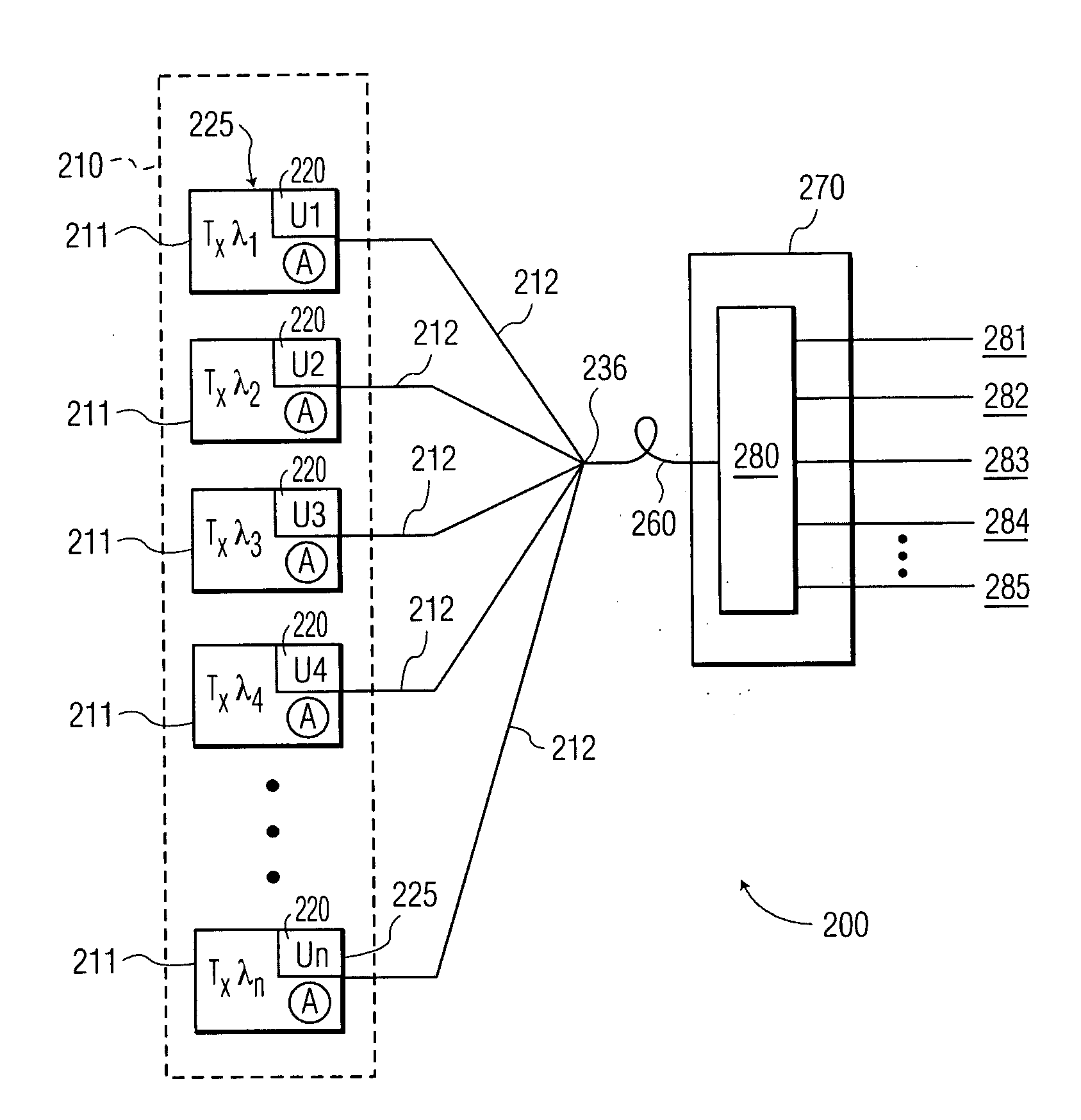
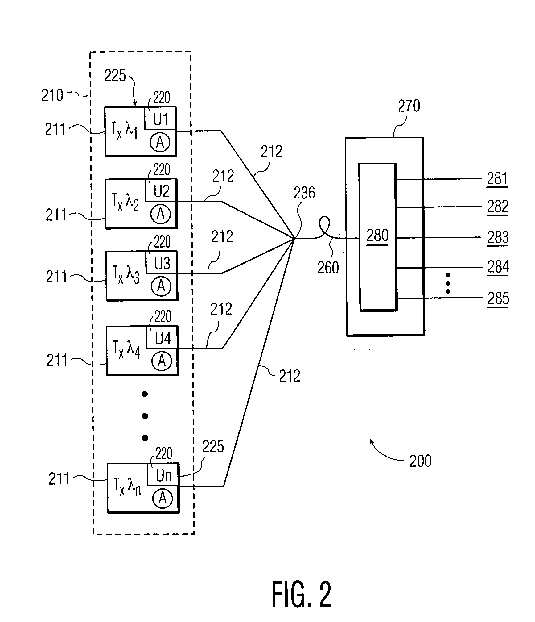
[0020] A first embodiment of a WDM optical transmission system 200 of the present invention is shown in FIG. 2 and comprises a cluster 210 of transmitters 220, a plurality of transmission fibers 212 operationally combined into a single transmission fiber 260, and a headend 270 including a receiver 280. Information is then removed from the receiver 280 as signals 281-285.

[0021] Each transmitter 220 operates at a particular wavelength, denoted by lambda 1, lambda 2, lambda 3, etc. Each transmitter 220 also includes an upconversion package 225, denoted by u1, u2, u3, etc., which upconverts the information in signal 211 to a particular frequency band. The upconverter may also be known by the term "signal re-spacer." ...


PUM


Abstract

A method and apparatus for a wavelength division multiplexing (WDM) optical transmission system wherein the optical transmission system has an optical signal transmitter which functions as a passive hub, in which only optical signal processing is performed, while associated electronic signal processing is performed outside the passive hub. The passive hub includes upconverter devices that place the optical signal bands at frequencies that allow separation of the bands at a detector. The detectors are thus loaded with more than one wavelength at a time. The optical transmission signals are optically combined and / or amplified onto a single fiber that is fed to a headend device, where the wavelengths of the optical transmission signals are demultiplexed and fed to the receivers.

Description

[0001] 1. Technical Field[0002] A method and apparatus for a wavelength division multiplexing (WDM) optical transmission system wherein the optical transmission system includes a passive hub in which only optical signal processing is performed, while associated electronic signal processing is performed outside the passive hub.[0003] 2. Related Art[0004] Optical or fiber optic transmission systems are well known. A typical optical transmission system is comprised of a physical entity at a central location known as a head-end, with one or more trunk lines extending therefrom. Each trunk line has a plurality of feeder lines extending therefrom into subscriber areas, where each subscriber is attached via a line tap onto the feeder or service line. When the distances between the head-end and the subscriber areas are substantial, intervening distribution hubs may be located along the trunk lines to replenish the strength and quality of the signal being provided to the subscribers.[0005] T...

Claims


Application Information

Patent Timeline
Patent Type & Authority Applications(United States)
IPC IPC(8): H04L12/44H04B10/27H04B10/272H04J14/00H04J14/02
CPCH04J14/0226H04J14/0282H04J14/0246H04J14/025H04B10/2581H04B10/25
Inventor SCHEMMANN, MARCEL F.C.MUTALIK, VENKATESH G.
Owner KONINKLIJKE PHILIPS ELECTRONICS NV
Why Eureka
Try Eureka