Wire spring forming apparatus

a technology of wire springs and forming apparatuses, which is applied in the direction of wire springs, domestic applications, other domestic objects, etc., can solve the problems of limiting the production rate and substantially lower production rate of prior art spring forming apparatuses, and achieves the effect of easy adjustment of the diameter of the coil spring

Active Publication Date: 2004-10-28
ORII & MEC
View PDF3 Cites 9 Cited by
  • Summary
  • Abstract
  • Description
  • Claims
  • Application Information

AI Technical Summary

Benefits of technology

[0006] It is, therefore, an object of the invention to overcome prior art problems mentioned above by providing a spring forming apparatus having a high production rate and being capable of easily adjusting the diameter of a coil spring to be formed.
[0007] The inventor has found that the aforementioned problems associated with prior art spring forming apparatuses can be solved as follows. First, rotation of the swivel table constituting a spring forming stage can be circumvented. This can be attained by allowing the feeding rollers holding the wire therebetween to revolve about the axis of the wire before a linear material, such as wire is fed therefrom to a spring forming stage ahead via a quill, thereby twisting and re-orienting the linear material. Thus, a multiplicity of bending tools need not be rotated and can be mounted on the table. This solution overcomes the second of the above-mentioned problems of low production rate. The first problem can be solved by providing a quill that can be moved in the axial direction of the linear material and electric motors adapted to numerically control the distance between the quill and the spring forming tools, thereby eliminating tedious manipulation of screws for adjusting the diameter of a coil to be formed. A trial spring forming apparatus based on these findings has been proven very efficient. Thus, the inventor has reached an inventive spring forming apparatus as disclose herein.

Problems solved by technology

However, the above-mentioned prior art apparatus has a drawback in that in adjusting the radius of the coil it is necessary to adjust the positions of the spring forming tools with respect to the quill by manipulating screws provided on the spring forming tools (Literature 1, Paragraph 0022 and FIG. 8), which is very tedious.
The prior art has another drawback in that the swivel table is provided with a set of 7 or 8 spring forming tools to attain high production efficiency.
Because of the large amount of time involved in such processes and large moment of inertia of the spring forming tools, the production rate of the prior art spring forming apparatus is substantially lower than it might otherwise be.
However, if more than one (2 say) such bending tools are mounted on the swivel table, an excessively large moment of inertia will result, so that in actuality only one bending tool can be mounted, which limits the production rate.

Method used


Image

  • Wire spring forming apparatus
  • Wire spring forming apparatus
  • Wire spring forming apparatus

Examples


Embodiment Construction

[0053] The invention will now be described in detail by way of examples with reference to the accompanying drawings.

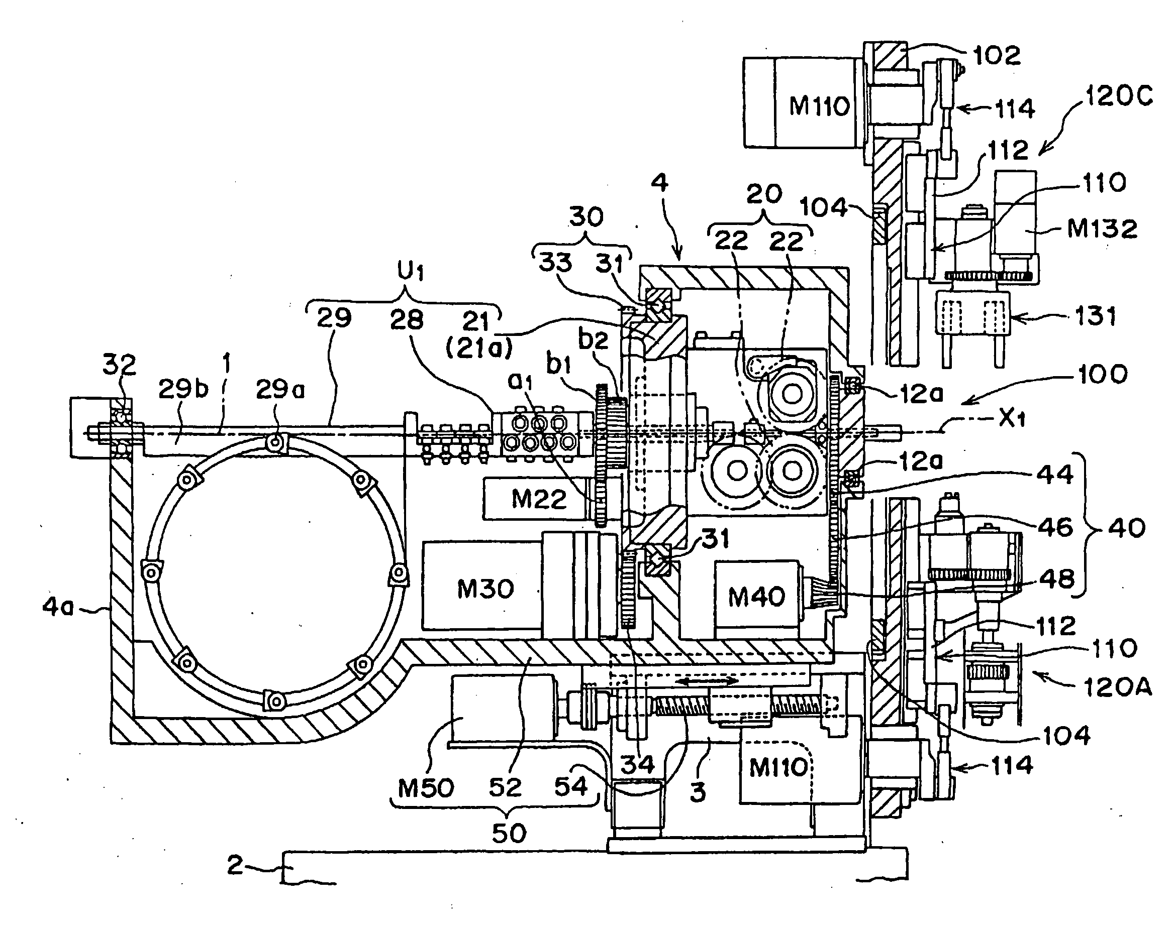
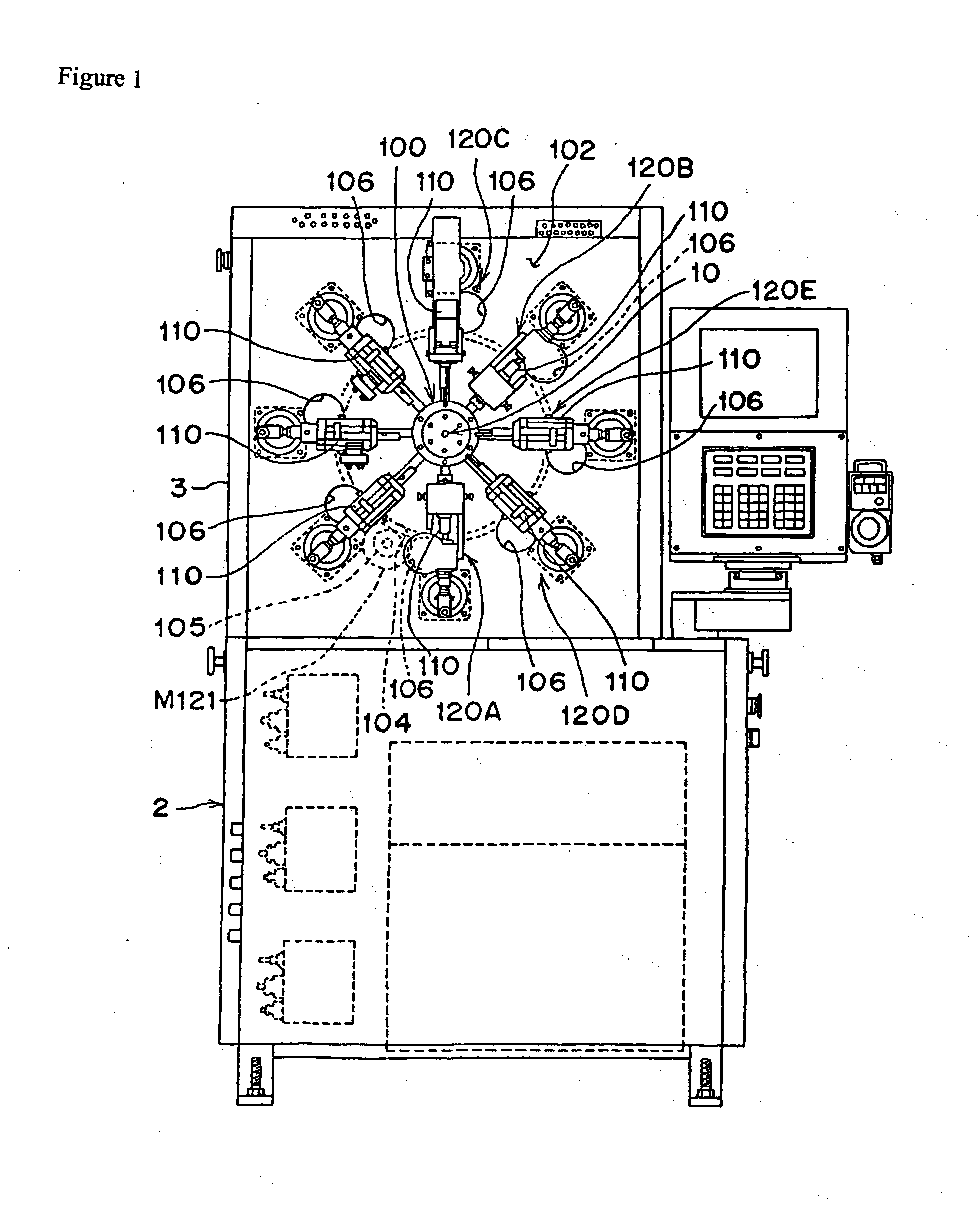
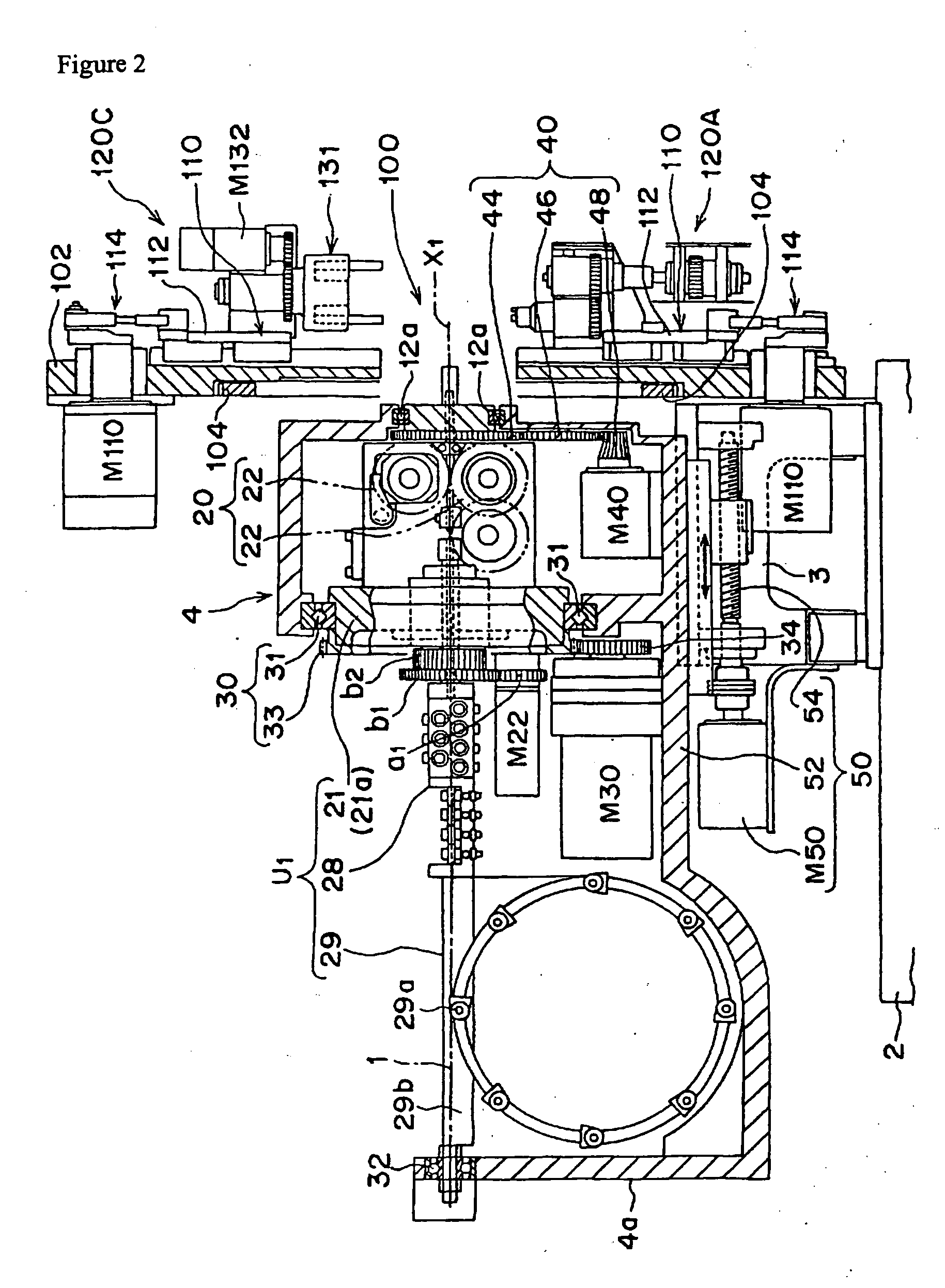
[0054] FIGS. 1-16 show a spring forming apparatus in accordance with a first embodiment of the invention. More particularly, FIG. 1 shows a front view of the apparatus; FIG. 2 shows a left elevation, partly in cross section; FIG. 3 shows a horizontal cross section of a portion of the apparatus including a rotational frame; FIG. 4 shows an enlarged cross section of the apparatus near the quill; FIG. 5 shows a front view of a bending tool of the spring forming apparatus; FIG. 6 shows a longitudinal cross section of the bending tool taken along line VI-VI of FIG. 5; FIG. 7 shows a perspective view of the main section of the bending tool; FIG. 8 shows a plan view of a coil forming tool; FIG. 9 shows a longitudinal cross sectional of the coil forming tool taken along line IX-IX of FIG. 8; FIG. 10 shows an arrangement of a dextral and a sinistral coil forming work heads form...


PUM

PropertyMeasurementUnit
angleaaaaaaaaaa
torqueaaaaaaaaaa
anglesaaaaaaaaaa

Abstract

A high-speed wire spring forming apparatus capable of easily adjusting a coil diameter is provided that includes: a wire feeder having a pair of feeding rollers (22) for feeding a wire (1) to a spring forming stage (100) via a quill (10) serving as a wire guide; a revolving mechanism (30) for revolving the feeding rollers (22) about the axis (X1) of the wire (1) to twist the wire (1) fed out of the leading end of the quill (10) to change the circumferential position, or angular position, of the wire (1); and a multiplicity of spring forming tools (120) arranged radially on a spring forming stage (100), each of the spring forming tools (100) movable in a direction substantially perpendicular to the axis (X1) of the wire (1).

Description

[0001] The invention relates to an apparatus for forming a wire spring, the apparatus having a multiplicity of radially arranged spring forming tools that can be advanced to a spring forming stage, perpendicularly to the axis of a wire fed or guided by a quill mounted on the spring forming stage, until the tools abut the wire provided at the leading ends of the quill, thereby forming the wire spring.[0002] Japanese Patent Early Publication H10-29028 discloses an apparatus having means for feeding a wire including feeding rollers from a front quill to a spring forming stage, and multiple types of radially arranged spring forming tools, which can be advanced perpendicularly or substantially perpendicularly to the axis of the wire towards the spring forming stage until they abut the wire coming out of the quill. The spring forming tools are mounted on a swivel table and can be positioned at predetermined angular positions by turning the swivel table through predetermined angles. By adv...

Claims


Application Information

Patent Timeline
Patent Type & Authority Applications(United States)
IPC IPC(8): B21F3/02B21F35/00B21F3/027B21F23/00B21F35/02
CPCB21F3/02B21F3/027B21F35/02
Inventor YAMAGUCHI, SINICHIHARUYAMA, NAOKI
Owner ORII & MEC
Why Eureka
Try Eureka