Image processor, image processing method, and recording medium on which image processing program is recorded

a technology of image processing and image data, applied in the field of image correction technology, can solve the problems of inability to apply the method to motion pictures, difficult to correct input image data in real time,

Inactive Publication Date: 2004-10-28
138 EAST LCD ADVANCEMENTS LTD
View PDF5 Cites 36 Cited by
  • Summary
  • Abstract
  • Description
  • Claims
  • Application Information

AI Technical Summary

Benefits of technology

[0029] In one aspect of the image processor, the correction on the input image data includes chroma correction that corrects two color difference data of the input image data, and the correction device performs correction on the two color difference data by time-divisionally referring to the same correction curve data. Since it is not necessary to hold correction curve data for every two color difference data, the required memory size can be reduced.

Problems solved by technology

As a result, it is difficult to correct the input image data in real time.
In particular, it is impossible to apply the method to motion pictures.

Method used


Image

  • Image processor, image processing method, and recording medium on which image processing program is recorded
  • Image processor, image processing method, and recording medium on which image processing program is recorded
  • Image processor, image processing method, and recording medium on which image processing program is recorded

Examples


first exemplary embodiment

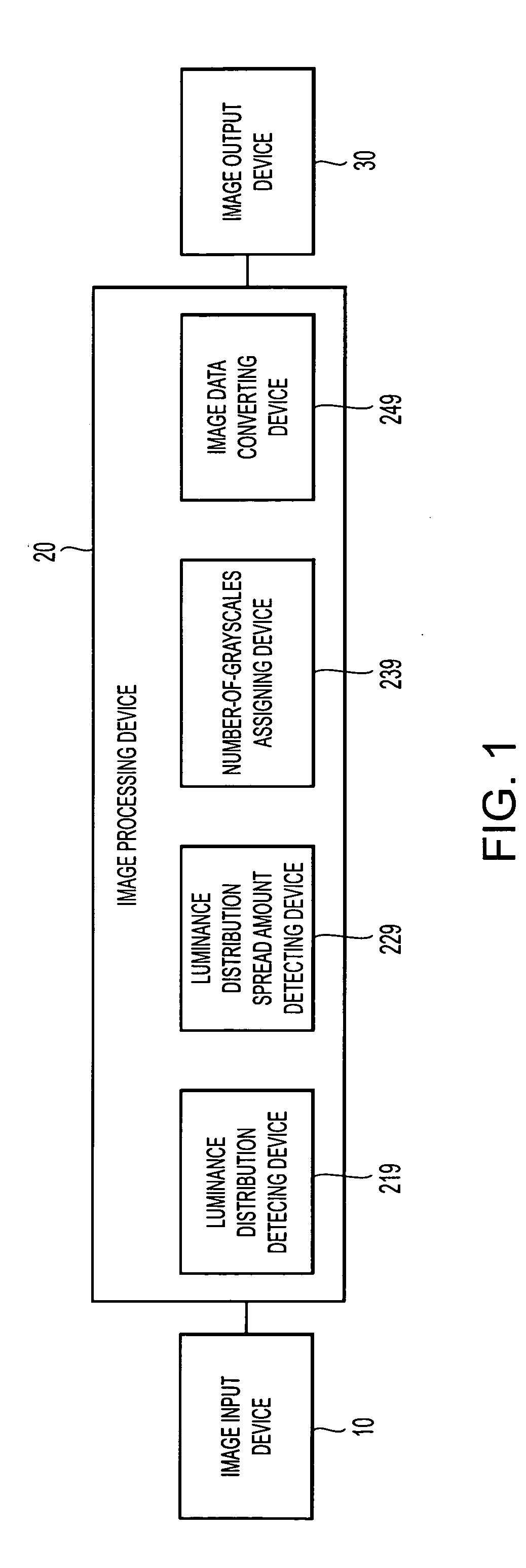
[0060] Next, a first exemplary embodiment of the present invention will be described. FIG. 3 illustrates an exemplary configuration of an image processor 20a according to the first exemplary embodiment of the present invention. The image processor 20a is an example of the image processor 20 shown in FIG. 1, receives an image input RGB_IN from the image input device 10, and outputs an image output RGB_OUT to the image output device 30.

[0061] As shown in FIG. 3, the image processor 20a according to the first exemplary embodiment of the present invention includes an RGB / YUV converting unit 201, a histogram creating unit 210, an image-statistic calculating unit 220, a correction amount calculating unit 230, a Y correction processing unit 240, and a YUV / RGB converting unit 202. Here, the configuration of FIG. 3 has such a relationship with the basic configuration of FIG. 1 that the histogram creating unit 210 corresponds to the luminance distribution detecting device 219, the image stati...

second exemplary embodiment

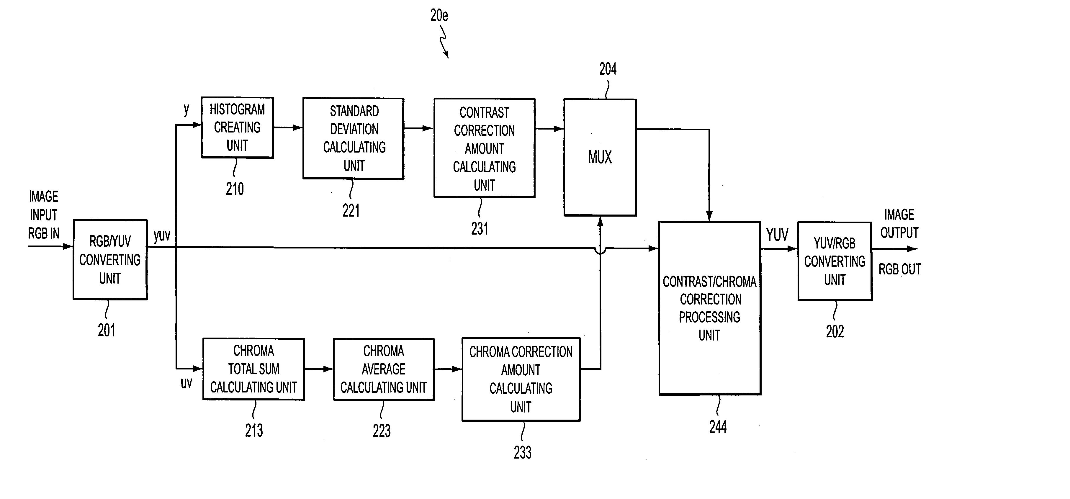
[0084] Hereinafter, a second exemplary embodiment of the present invention will be described. The second exemplary embodiment relates to an image processing system when image correction, more specifically contrast correction, is performed using a correction curve. Here, contrast correction is directed to enhancing contrast by decreasing a grayscale value of a pixel having low luminance and by increasing a grayscale value of a pixel having high luminance with respect to the Y (luminance) data of the input image.

[0085] FIG. 6 illustrates an exemplary configuration of an image processor 20b according to the second exemplary embodiment of the present invention. The basic configuration of the image processor 20b according to the second exemplary embodiment of the present invention is similar to that of the image processor 20a according to the first exemplary embodiment shown in FIG. 3. However, the image processor 20b is different from the image processor 20a in that a standard deviation...

third exemplary embodiment

[0102] Hereinafter, a third exemplary embodiment of the present invention will be described. The third exemplary embodiment relates to an image processing system in which image correction, particularly, brightness correction using a correction curve is performed. Brightness correction is performed when the entire luminance distribution of Y (luminance) data of an input image inclines toward low luminance or high luminance.

[0103] FIG. 9 illustrates the configuration of an image processor 20c according to the third exemplary embodiment of the present invention. The basic configuration of the image processor 20c according to the third exemplary embodiment is similar to that of the image processor 20a according to the first exemplary embodiment shown in FIG. 3. Specifically, the image processor 20c includes an RGB / YUV converting unit 201, a luminance total sum calculating unit 212, a luminance average calculating unit 222, a brightness correction amount calculating unit 232, a Y correct...


PUM


Abstract

To provide an image processor, an image processing method, and an image processing program which make it possible to perform high-speed image correction suitable for motion pictures while reducing a memory resource, etc., an image processor that corrects input image data having a predetermined grayscale range is provided. The image processor includes a coefficient holding device to hold correction coefficients of a correction curve that corresponds to the entire grayscale range or a portion of the grayscale range and includes one or more correction points and a combination portion that is formed of a combination of a plurality of specific curve pattern portions, a correction amount determination device to determine a correction amount based on statistical information of grayscale values of pixels in the image input data, and a correction device to correct the input image data by adding the product of the correction amount and the correction coefficients determined by the input image data to the input image data.

Description

[0001] 1. Field of Invention[0002] The present invention relates to an image correction technology that performs correction processes on input images from various sources.[0003] 2. Description of Related Art[0004] There are image processors that receive image data from various image input devices, such as digital cameras, and perform correction processes, e.g., a contrast correction process and a luminance correction process. In such an image correction process, the grayscale of an input image is generally corrected according to a predetermined correction curve. Specifically, correction curve data that specifies a correction curve is previously stored in a memory, such as a lookup table (LUT), and input image data correction is performed with reference to the LUT.[0005] Also, a method of determining a correction curve according to the contents of input image data, e.g., luminance distribution, has been suggested. See Japanese Unexamined Patent Application Publication No. 10-208034.[...

Claims


Application Information

Patent Timeline
Patent Type & Authority Applications(United States)
IPC IPC(8): G06T1/00G06T5/40G06T5/00H04N1/40H04N1/407H04N1/46H04N1/60H04N5/20H04N9/68
CPCG06T5/009G06T5/40G06T2207/20008G06T2207/10024G06T2207/10016F16L41/12F16L41/088F16B2/065
Inventor MORI, KENJI
Owner 138 EAST LCD ADVANCEMENTS LTD
Why Eureka
Try Eureka