Wireless LAN access point apparatus
a technology of access point and access point apparatus, which is applied in the direction of instruments, data switching networks, wireless commuication services, etc., can solve the problems of inability to contribute to the location determination of the terminal, the degradation of accuracy and reliability of the terminal locating arithmetic procedure executed by the server 6, and the inability to store noise signals in memory spa
- Summary
- Abstract
- Description
- Claims
- Application Information
AI Technical Summary
Problems solved by technology
Method used
Image

Examples
first embodiment
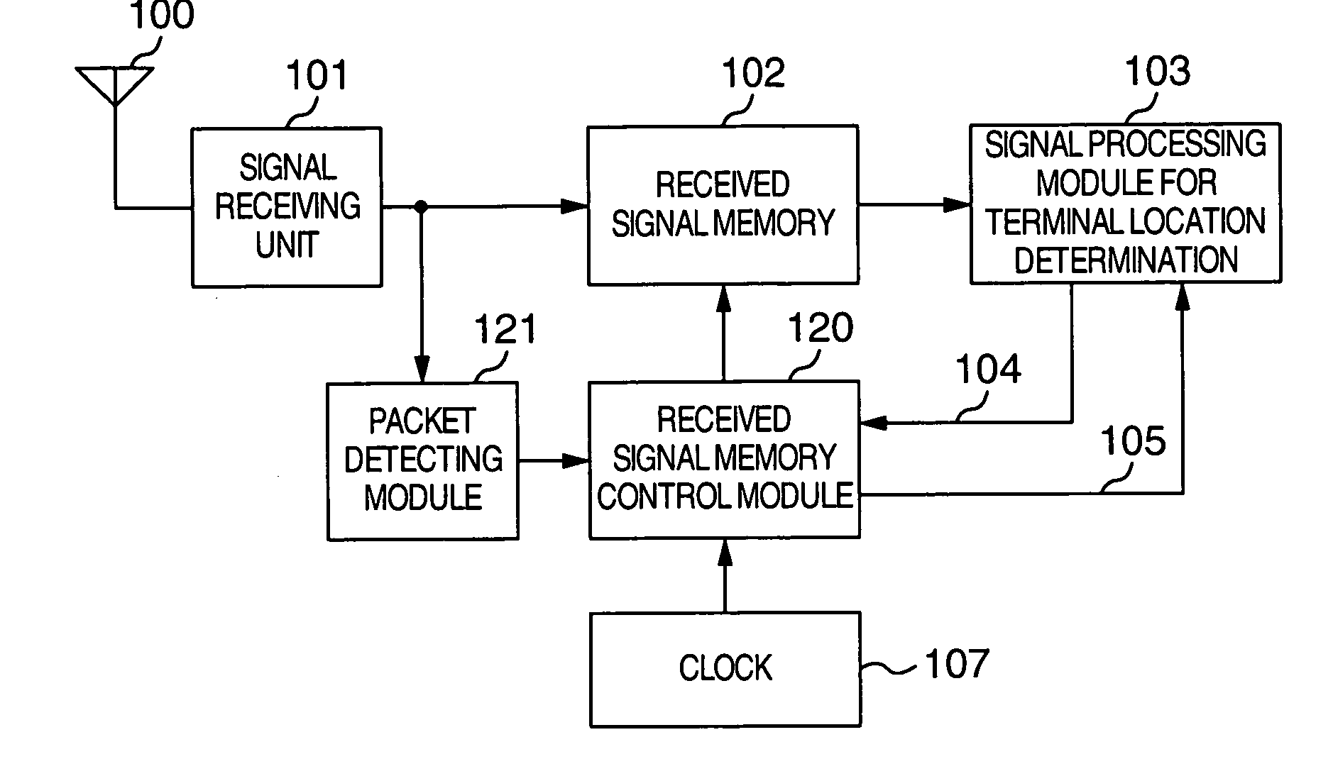
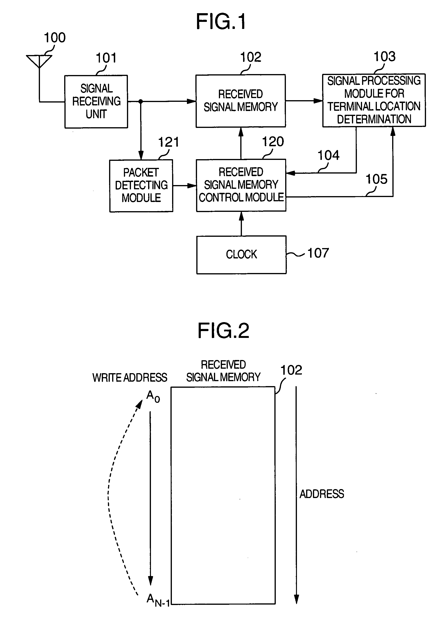
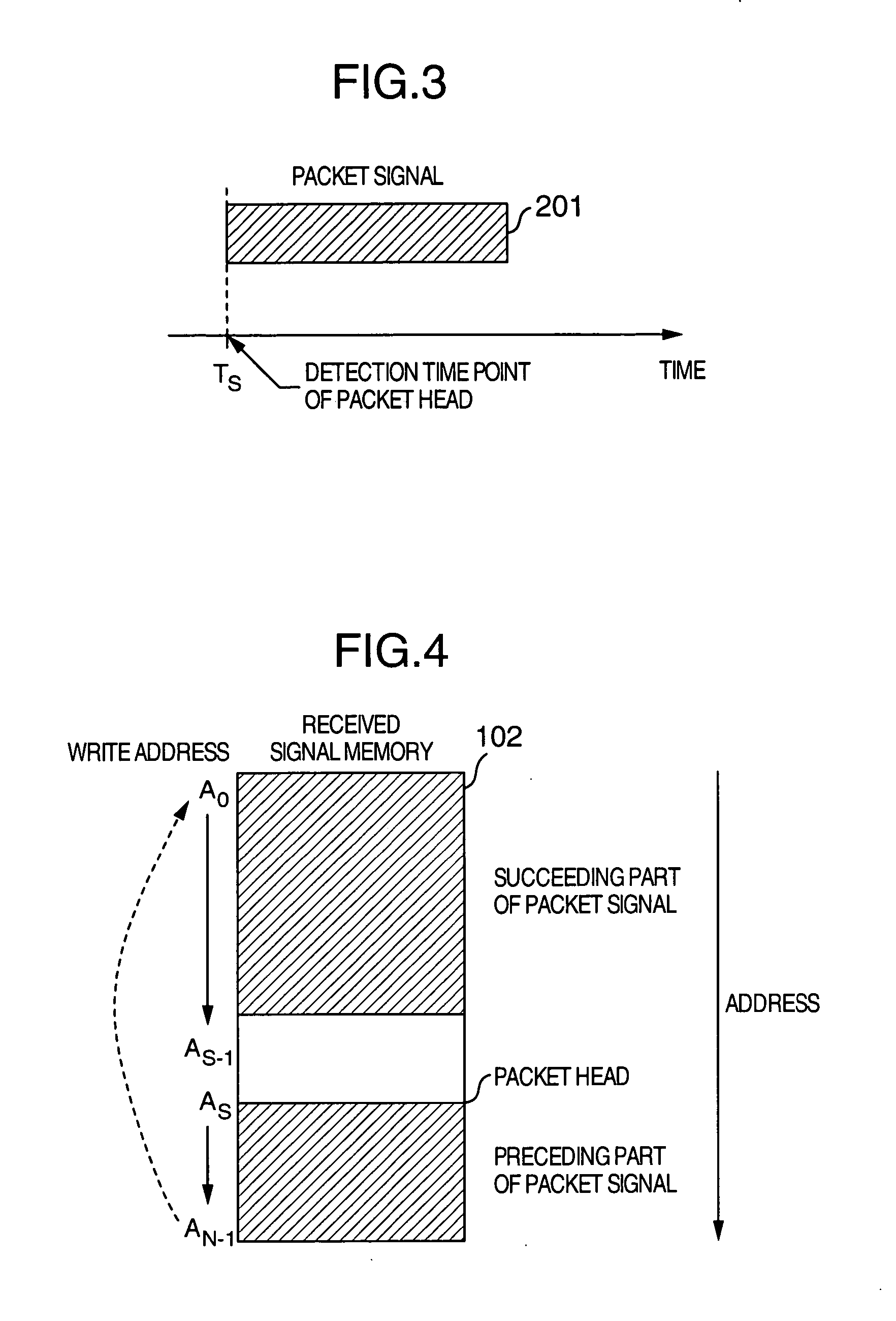
[0043] Now referring to FIGS. 3 and 4, description will be directed to a method of stopping the capture of the received signal through cooperation of the packet detecting module 121 and the received signal memory control module 120 according to the present invention. As shown in FIG. 3, the packet detecting module 121 is designed to detect a leading portion or edge of a packet signal 201 arrived at the access point apparatus (base station) at a timing T.sub.S and message the detection of the packet head to the received signal memory control module 120. For detecting the leading edge of the packet signal, there can be mentioned a method of making decision as to whether or not the received power increases steeply beyond a threshold value, to thereby determine the detection of the leading edge of the packet signal when the threshold value is exceeded. Alternatively, such a detection method may equally be adopted according to which a correlation value of the received signal and a predet...
second embodiment
[0044] Next, referring to FIGS. 5 and 6, description will be directed to the method of stopping the capture of the received signal effected through cooperation of the packet detecting module 121 and the received signal memory control module 120 according to the present invention. As shown in FIG. 5, the packet detecting module 121 is designed to detect a trailing portion or edge of a packet signal 202 arrived at the access point apparatus (base station) and message the detection of the packet end to the received signal memory control module 120. For detecting the trailing edge of the packet signal, there can be mentioned a method of making decision as to whether or not the received power decreases steeply below a threshold value, to thereby determine the detection of the trailing edge of the packet signal when the received power becomes lower than the threshold value. Upon reception of the message informing the detection of the packet end from the packet detecting module 121, the re...
third embodiment
[0045] Referring to FIGS. 7 and 8, description will be directed to the method of stopping the capture of the received signal effected through cooperation of the packet detecting module 121 and the received signal memory control module 120 according to the present invention. Referring to FIG. 7, the packet detecting module 121 detects a packet signal 203 arrived at the access point apparatus (base station) at an intermediate portion of the packet (timing T.sub.p) and messages the detection of the packet to the received signal memory control module 120. For detecting the packet at the intermediate portion thereof, as mentioned above, there can be adopted, for example, a method of monitoring the received signal power for a predetermined period and making decision as to whether or not a mean value of the received power exceeds a threshold value. When the mean value of the received power exceeds the threshold value, it can then be decided that the packet signal has been detected. Upon re...
PUM
 Abstract
Description
Claims
Application Information
 - R&D
- Intellectual Property
- Life Sciences
- Materials
- Tech Scout
- Unparalleled Data Quality
- Higher Quality Content
- 60% Fewer Hallucinations
Browse by: Latest US Patents, China's latest patents, Technical Efficacy Thesaurus, Application Domain, Technology Topic, Popular Technical Reports.
© 2025 PatSnap. All rights reserved.Legal|Privacy policy|Modern Slavery Act Transparency Statement|Sitemap|About US| Contact US: help@patsnap.com