Optical pickup

a pickup and optical technology, applied in the field of optical pickups, can solve the problems of reducing the discarding cost, unable to meet the needs of laser diodes, and the possibility of thermal expansion and deformation of the synthetic resin-made base by the heat generation of the laser diodes

Inactive Publication Date: 2004-11-04
FUNAI ELECTRIC CO LTD
View PDF5 Cites 14 Cited by
  • Summary
  • Abstract
  • Description
  • Claims
  • Application Information

AI Technical Summary

Problems solved by technology

Accordingly, it is possible to reuse a diffraction grating and the base separated from the defective laser diode, so that the discarding cost decreases.
In addition, since the base is isolated from the heat generation of the laser diode by means of the holder, and the holder and the base are merely in partial contact with each other, there is no possibility of the synthetic resin-made base being thermally expanded and deformed by the heat generation of the laser diode.

Method used


Image

  • Optical pickup
  • Optical pickup
  • Optical pickup

Examples


Embodiment Construction

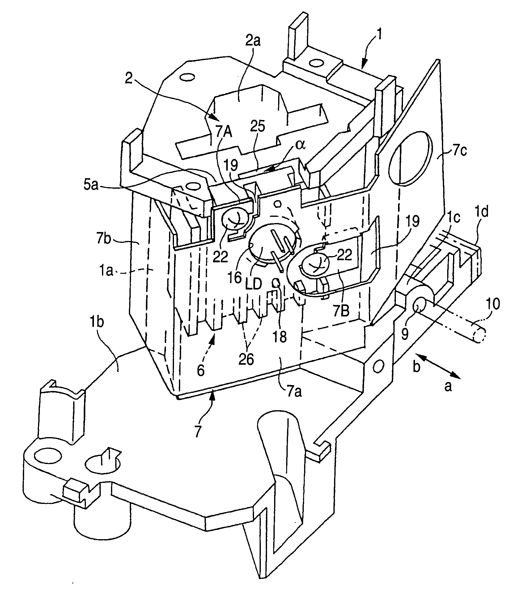
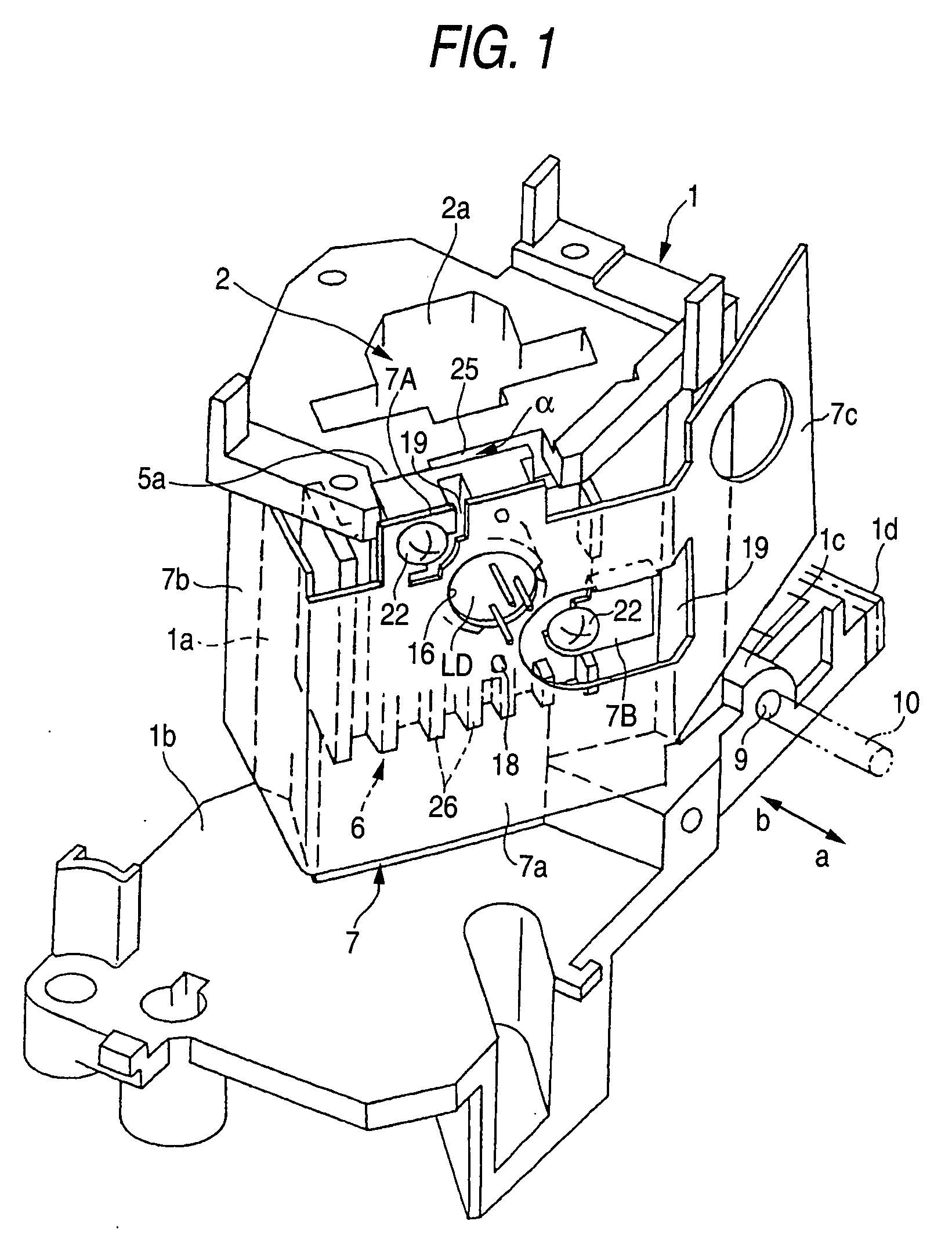
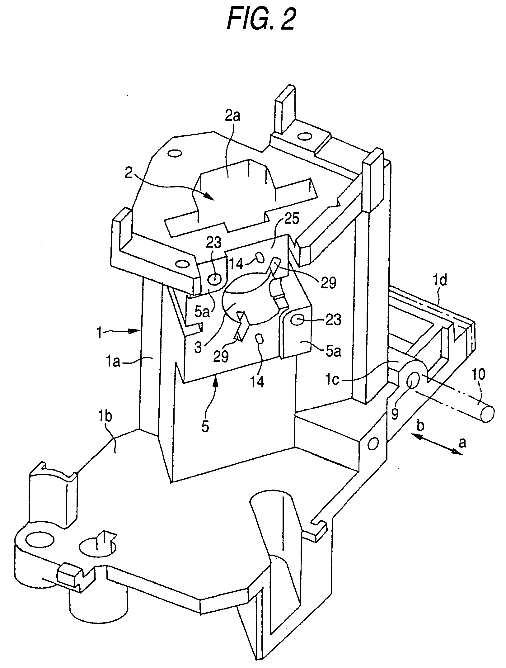
[0051] FIGS. 1 to 7 show an optical pickup in accordance with an embodiment of the invention. This optical pickup has a metallic holder 6 which is retained on a laser mounting surface 5 formed at a periphery of an opening of a laser hole 3 of a base 1, as well as a metallic radiating plate 7 which is attached to an outer surface of the holder 6. Since the construction other than the one described above is substantially identical to that shown in FIGS. 13 to 14B, identical portions will be denoted by the same reference numerals, and a description thereof will be omitted.

[0052] The base 1 is formed of a hard synthetic resin, and, as shown in FIGS. 1 to 7, includes a tubular base body 1a with the laser mounting surface 5 formed thereon, a base plate portion 1b formed integrally with the base body 1a, and a pair of brackets 1c and a rack 1d which are projectingly provided as a unit on the base plate portion 1b. A guide rod 10 is movably fitted in through holes 9 of the brackets 1c, and ...


PUM

PropertyMeasurementUnit
diameteraaaaaaaaaa
point symmetryaaaaaaaaaa
forceaaaaaaaaaa

Abstract

An optical pickup includes a radiating plate made to abut against a rear surface of a laser diode by positioning an engaging hole provided penetratingly in a central portion of the radiating plate concentrically with the laser diode. Slits are formed in the radiating plate to form a pair of tongues in the manner of point symmetry about an axis of the engaging hole. Screw insertion portions formed in the respective tongues are communicates with the slits. As screws are passed through the screw inserting portions and are screwed in, the radiating plate is secured to the base. When the screws are screwed in, the axis is positioned on a phantom line connecting points of application of force generated at proximal end portions of the tongues. Distances from the axis to the respective points of application of force are set to be substantially identical.

Description

[0001] 1. Field of the Invention[0002] The present invention relates to an optical pickup for use in a disk player such as a DVD player.[0003] 2. Description of the Related Art[0004] Conventionally, as techniques of optical pickups, those disclosed in JP-A-11-16205 and the like are known. One such example will be explained with reference to FIG. 13. A photodiode PD is disposed at one end opening 2a of a light passage hole 2 provided penetratingly in a synthetic resin-made base 1 in which a half mirror HM is disposed. A collimator lens QWP and an objective lens OL are disposed in its other end opening 2b, and a laser diode LD and a diffraction grating G are disposed in a laser hole 3 communicating with the light passage hole 2. Laser light is projected from the laser diode LD onto a disk D through the half mirror HM, the collimator lens QWP, and the objective lens OL, and its reflected light is received by the photodiode PD through the half mirror HM to thereby read information recor...

Claims


Application Information

Patent Timeline
Patent Type & Authority Applications(United States)
IPC IPC(8): G11B7/08G11B7/00G11B7/085G11B7/09G11B7/12G11B7/125H01S5/022H01S5/024
CPCG11B7/08582G11B7/0933G11B7/12
Inventor SOGAWA, TERUAKIMORI, FUMIAKITANABE, NORITAKA
Owner FUNAI ELECTRIC CO LTD
Why Eureka
Try Eureka