System and process for treating waste gas employing bio-treatment technology

a bio-treatment technology and waste gas technology, applied in the direction of moving filter element filters, separation processes, filtration separation, etc., can solve the problems of increasing the pressure loss, affecting the flow of the reactor, and limiting the use of bio-treatment technology

Inactive Publication Date: 2004-11-04
NAT CHIAO TUNG UNIV
View PDF2 Cites 13 Cited by
  • Summary
  • Abstract
  • Description
  • Claims
  • Application Information

AI Technical Summary

Problems solved by technology

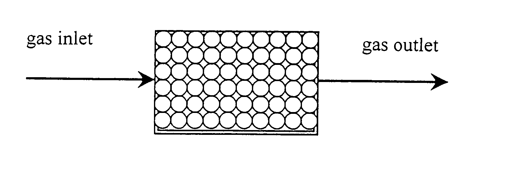
Conventional biological technology for treating waste gas, such as a biofilter and a biotrickling filter, can only deal with the waste gas having little or no dust/grease.
When the waste gas to be treated contains dust/grease, it will clog the biofilter, reduce the activity of the microorganisms (or activated sludge), cause the short flow of the reactor, increase the pressure loss, decrease the treating efficiency and shorten the service life of the bioreactor.
Therefore, the conventional biological technology for treating waste gas is often limited to the application of treating waste gas in a specific field.
However, for the type of "flow upward," it is not easy to control the humidity of the filter materials, which often causes the deficiency of the humidity for the filter materials at the inlet of the reactor.
In addition, because the type of "flow upward" takes an opposi

Method used


Image

  • System and process for treating waste gas employing bio-treatment technology
  • System and process for treating waste gas employing bio-treatment technology
  • System and process for treating waste gas employing bio-treatment technology

Examples


Embodiment Construction

[0012] The preferred embodiment of the claimed invention is illustrated in FIG. 4, and comprises a conventional biotrickling filter system, in association with a dust / grease filtering device 1, a two-way directionally gas inlet system 5, a bioaerosol removal device 9 and a cell immobilization unit 11.

[0013] The conventional biotrickling filter system primarily includes a liquid spraying reservoir 12, a plurality biological reactors 13, a nutritional salt preserving reservoir 14 for furnishing nutrition that is required at the growth of microorganism. The periphery of the system includes a ventilating far 2, a flow meter 3, pressure drop meters 6, a liquid filtering device 7, a liquid circulating flow water pump 8, sampling holes 10.

[0014] According to the preferred embodiment, the waste gas to be treated enters the dust / grease filtering device 1. By means of conveyance due to the ventilating fan 2, the waste gas is conveyed from the flow meter 3 and the two-way directional gas inlet...


PUM

PropertyMeasurementUnit
Mesh sizeaaaaaaaaaa
Pressureaaaaaaaaaa
Shapeaaaaaaaaaa

Abstract

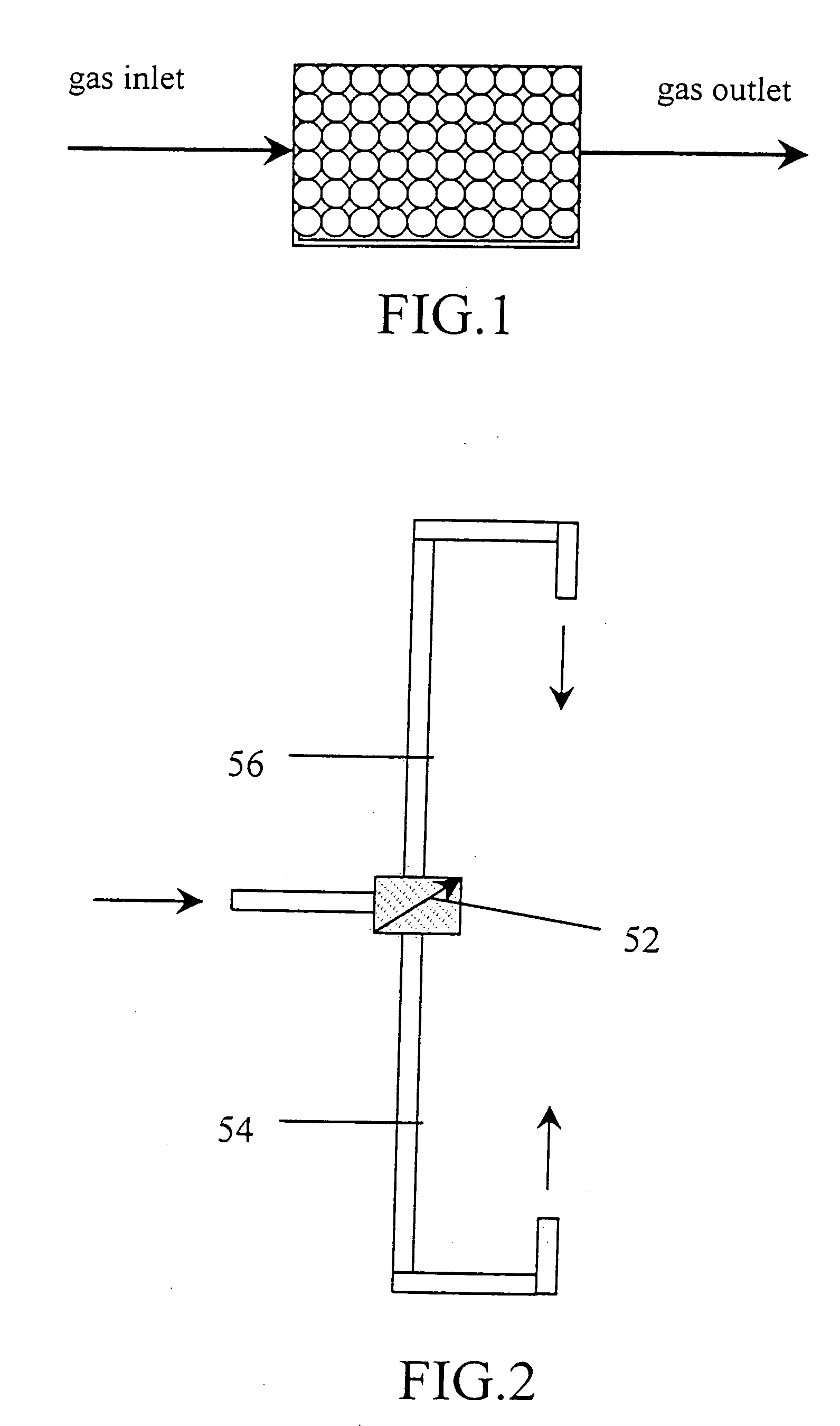
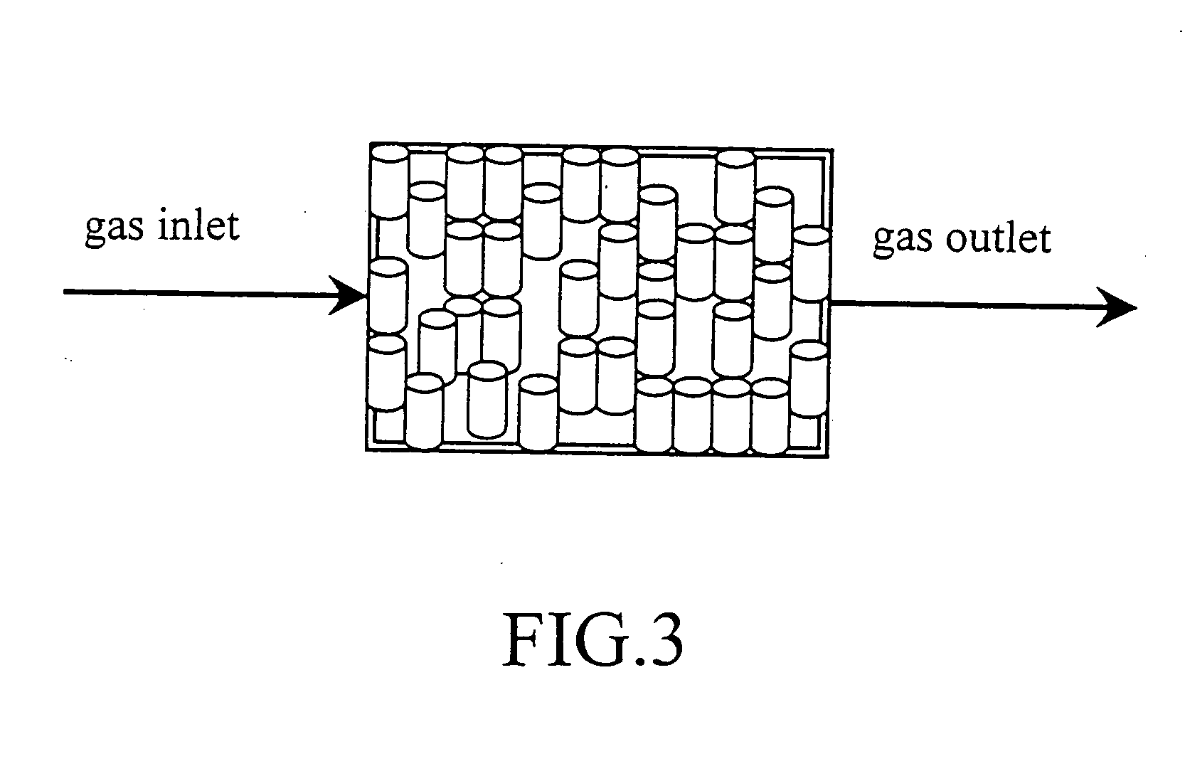
A system and process of bio-treatment for enhancing the efficiency of treating waste gas is disclosed. This technology relates to an application of a dust/grease filtering device, a two-way directionally gas inlet system, a bioaerosol removal device, and a cell immobilization technology, to a conventional bioreactor for treating waste gas. The dust/grease filtering device is formed by fillers which form pores being less than 100 mesh, in order to efficiently remove the majority of dust/grease existing in the waste gas, and reduce the pressure drop of the reactor. The two-way directionally gas inlet system can control the direction of the gas flowing into the bioreactor, in order to efficiently control the pressure drop, and the variation of pH value and the humidity in the reactor. The cell immobilized technology makes a connection between support and microorganisms offering the biological reaction, in order to enhance the activity and living percentage of the microorganisms in the biotrickling filter, and reduce the emission of the bioaerosol. The bioaerosol removal device is filled with the fillers having the function of sterilization. After the waste gas is treated and before it is exhausted to the environment, the filler may remove the bioaerosol existing therein, thereby improving the safety and widening the application field of the waste gas bio-treatment system.

Description

[0001] The present invention relates to an improved waste gas treatment system and process.DESCRIPTION OF THE RELATED ART[0002] Conventional biological technology for treating waste gas, such as a biofilter and a biotrickling filter, can only deal with the waste gas having little or no dust / grease. When the waste gas to be treated contains dust / grease, it will clog the biofilter, reduce the activity of the microorganisms (or activated sludge), cause the short flow of the reactor, increase the pressure loss, decrease the treating efficiency and shorten the service life of the bioreactor. Therefore, the conventional biological technology for treating waste gas is often limited to the application of treating waste gas in a specific field.[0003] Nowadays the types for waste gas entering a bioreactor include "flow upward (i.e., flowing upward from the bottom of the reactor)" and "flow downward (i.e., flowing downward from the top of the reactor)." The type of "flow upward" can better con...

Claims


Application Information

Patent Timeline
IPC IPC(8): B01D46/30
CPCB01D46/30B01D46/0023B01D46/62
Inventor TSENG, CHING-PINGCHUNG, YING-CHIEN
Owner NAT CHIAO TUNG UNIV
Why Eureka
Try Eureka