Milling cutter having three continuously curved cutting edges

Active Publication Date: 2004-11-11
SECO TOOLS AB
View PDF14 Cites 11 Cited by
  • Summary
  • Abstract
  • Description
  • Claims
  • Application Information

AI Technical Summary

Benefits of technology

0006] Another object of the present invention is to provide a milling cutter, which combines the advantages achieved by using round inserts with good strength.
0007] Still another object of the present invention is to prov

Problems solved by technology

However, it has turned out that during milling of, e.g., moulds in tool steel, that the cutting rate during face milling is not especially large.
Furthermore, vibrations arise

Method used


Image

  • Milling cutter having three continuously curved cutting edges
  • Milling cutter having three continuously curved cutting edges
  • Milling cutter having three continuously curved cutting edges

Examples


Embodiment Construction

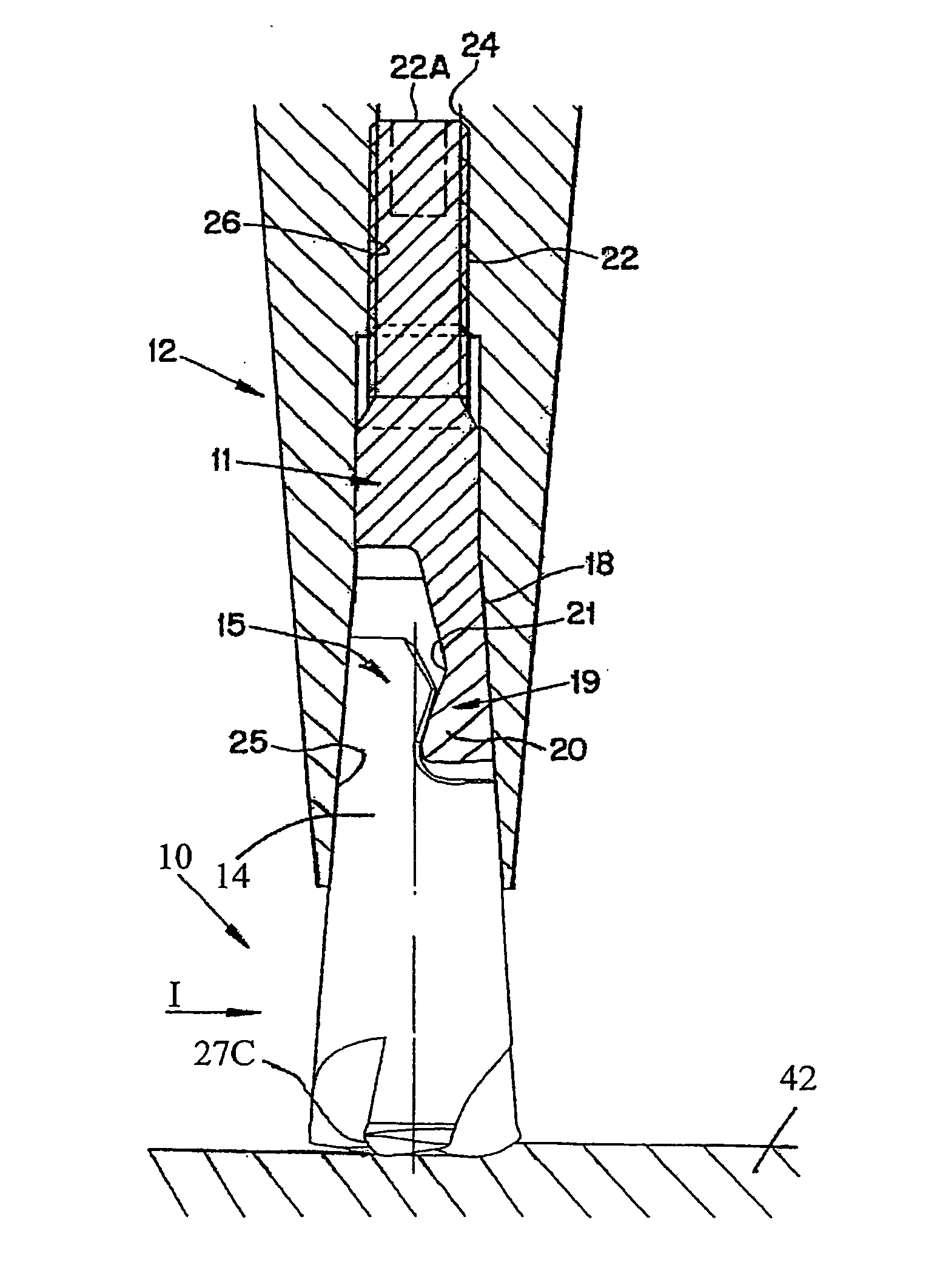
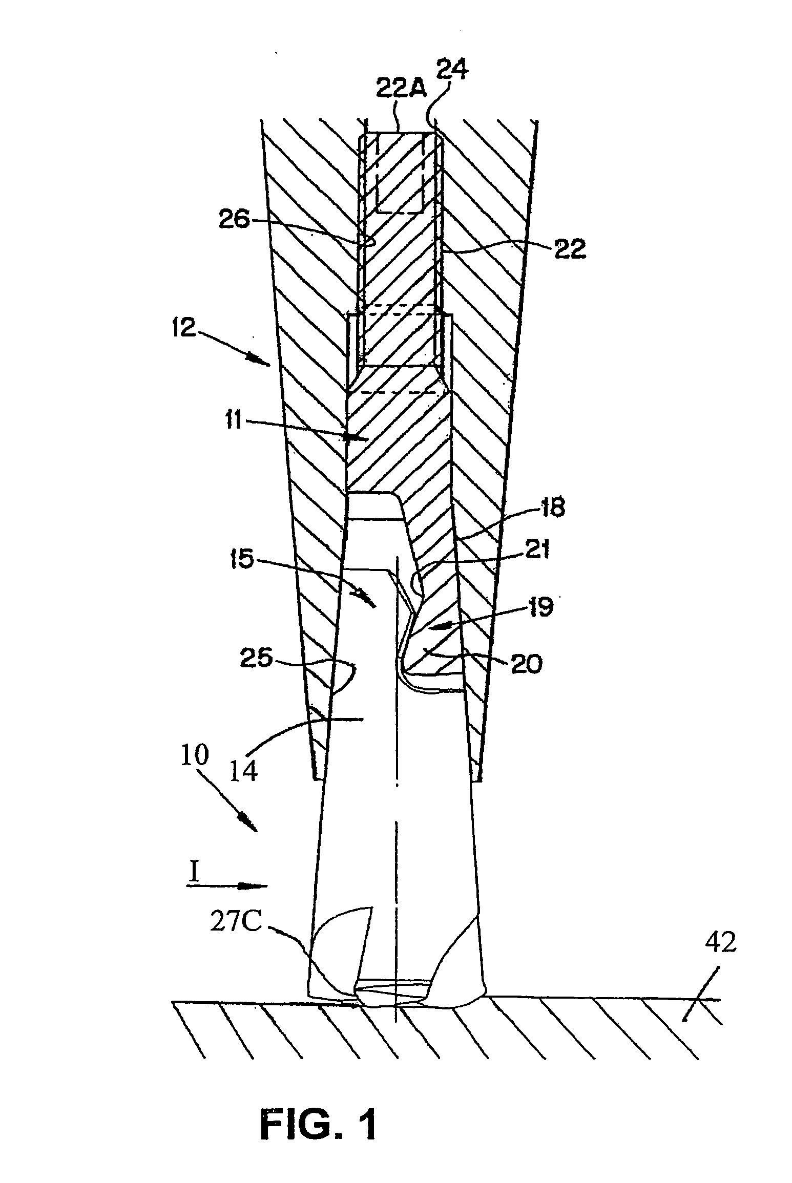
[0019] The embodiment of a tool shown in FIG. 1 comprises a milling cutter 10 according to the present invention, a locking screw 11 as well as a holder 12. The tool comprises hook-shaped couplers 15, 19 arranged on the milling cutter and the locking screw, respectively. The coupler 15 defines a fastening end of the cutter.

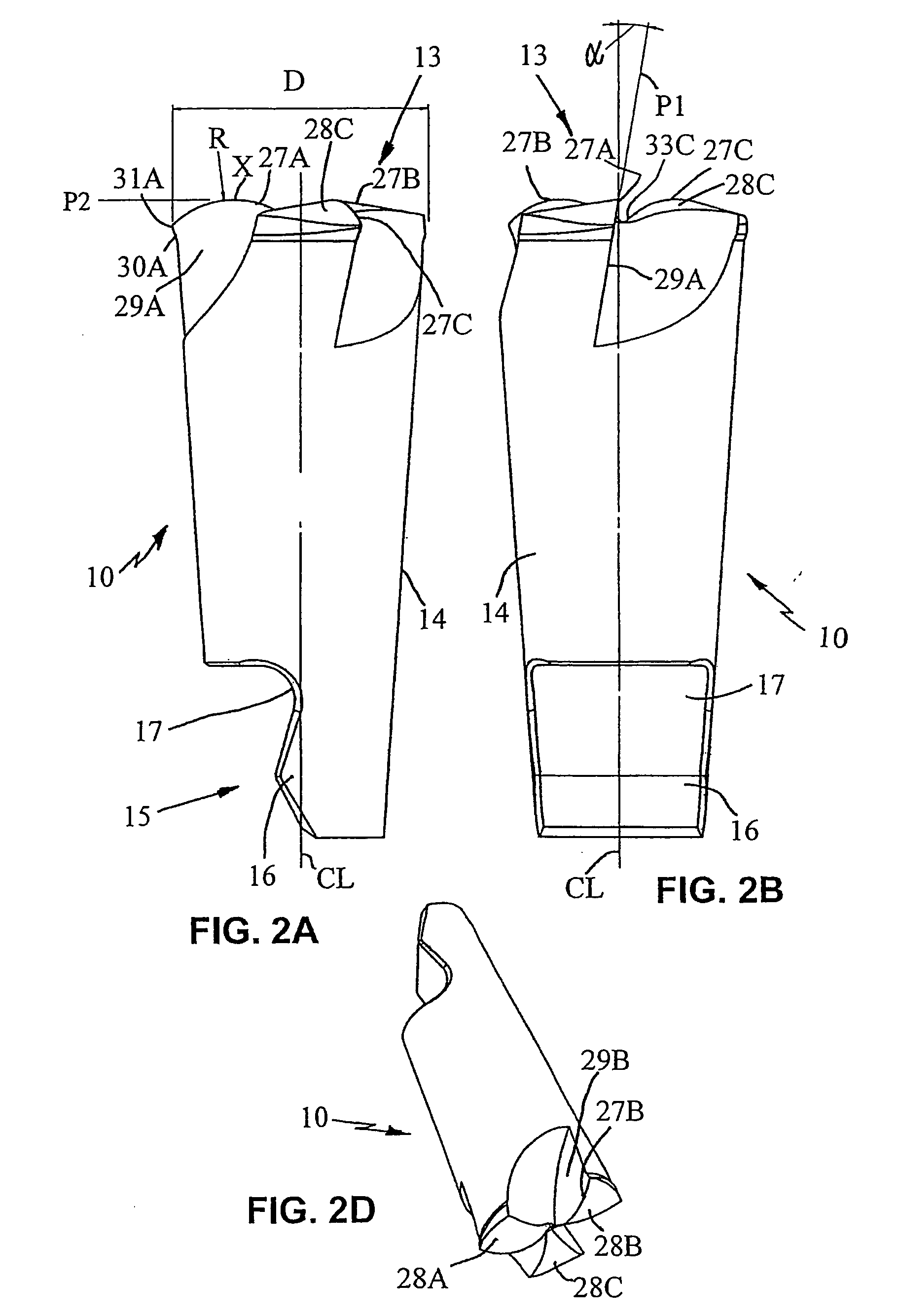
[0020] The milling cutter 10 is, at the end thereof facing away from the holder 12, provided with a cutting end 13 provided with three cutting edges. A preferred form of the milling cutter 10 is shown more in detail in FIGS. 2A-2E. The milling cutter 10 is manufactured from hard material, preferably cemented carbide, and comprises a body having three integrated cutting edges 27A, 27B and 27C, i.e., the cutting edges are defined by the body itself as opposed to being defined by a separately attached insert. The most common hard material in cemented carbide is tungsten carbide, TC. Many cemented carbide sorts contain only TC and binder metal. In others, carbides of ...


PUM

PropertyMeasurementUnit
Fractionaaaaaaaaaa
Diameteraaaaaaaaaa
Shapeaaaaaaaaaa

Abstract

A milling cutter includes a body having three cutting edges formed by the body. An end of the body situated opposite the cutting edges defines a fastening end of the milling cutter. Each cutting edge extends from an outer periphery of the body substantially to a center rotational axis of the body along a substantially convexly curved path. Radially outer and radially inner ends of each cutting edge are situated axially rearwardly of an axially foremost point of the cutting edge. Each cutting edge lies on a respective imaginary sphere having a radius which has a center which that is spaced from the cutting edge in a direction toward the fastening end and spaced radially from the center axis.

Description

[0001] This application claims priority under 35 U.S.C. .sctn..sctn. 119 and / or 365 to Patent Application Serial No. 0300313-4 filed in Sweden on Feb. 6, 2003, the entire content of which is hereby incorporated by reference.[0002] The present invention relates to a milling cutter for rotary cutting machining.[0003] It is previously known by the applicant's U.S. Pat. No. 5,964,555 to provide a solution to the problem of making milling tools in small dimensions having replaceable cutting edges. However, it has turned out that during milling of, e.g., moulds in tool steel, that the cutting rate during face milling is not especially large. Furthermore, vibrations arise during use of the known tool.[0004] Furthermore, it is known to provide shank-type cutters having screwed-in round cutting inserts in order to, among other things, be used during face milling. Since it most often concerns small dimensions, the hollow cutting inserts become relatively weak, which has manifested itself in t...

Claims


Application Information

Patent Timeline
IPC IPC(8): B23C5/10B23C5/02
CPCB23C5/10B23C2210/03B23C2210/084B23C2222/28Y10T407/1964Y10T407/1948Y10T408/907Y10T409/30952Y10T408/9095Y10T407/1908
Inventor BERGLOW, CARL-ERIKPUIDE, MATTIASPERSSON, SVEN-ERIKNORDLUND, KURT
Owner SECO TOOLS AB
Why Eureka
Try Eureka