Ultrasonic sensor

a technology of ultrasonic sensor and sensor, which is applied in the direction of mechanical vibration separation, instruments, specific gravity measurement, etc., can solve the problems of reverberation, reduced detection accuracy of ultrasonic sensor, and inability to detect obstacles

Inactive Publication Date: 2004-11-18
DENSO CORP +1
View PDF8 Cites 74 Cited by
  • Summary
  • Abstract
  • Description
  • Claims
  • Application Information

AI Technical Summary

Problems solved by technology

However, the above ultrasonic sensor has a disadvantage that a reverberation occurs after normal vibration of the piezoelectric vibrator.
Therefore, detection accuracy of the sensor may be reduced and the ultrasonic sensor may not be able to detect an obstacle at a short distance if the reverberation continues long.
However, characteristics of the piezoelectric vibrator J1 and the capacitor J2 are uneven.
Accordingly, a temperature compensation cannot be performed correctly and a temperature drift occurs.
Further, a temperature range to compensate for electric capacity

Method used


Image

  • Ultrasonic sensor
  • Ultrasonic sensor
  • Ultrasonic sensor

Examples


first embodiment

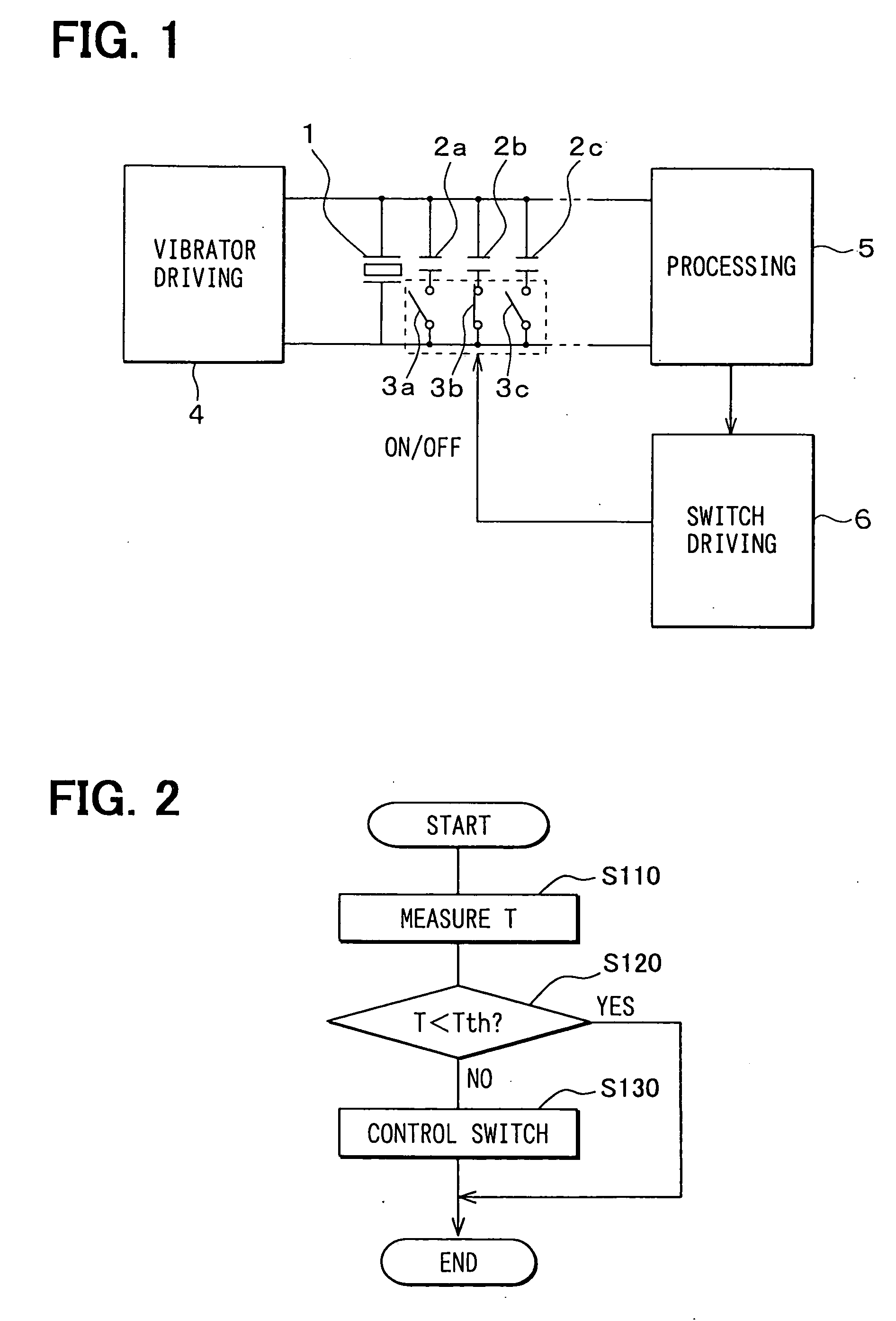
[0024] In FIG. 1, an ultrasonic sensor is applied as an obstacle detection sensor for both transmitting and receiving an ultrasonic wave. For example, this obstacle detection sensor is mounted in a vehicle and detects an obstacle near the corners of the vehicle. This obstacle detection sensor transmits an ultrasonic wave from a piezoelectric vibrator 1 and receives a reflected wave from an obstacle corresponding to a detection object. Thus, this obstacle detection sensor detects an existence of an obstacle.

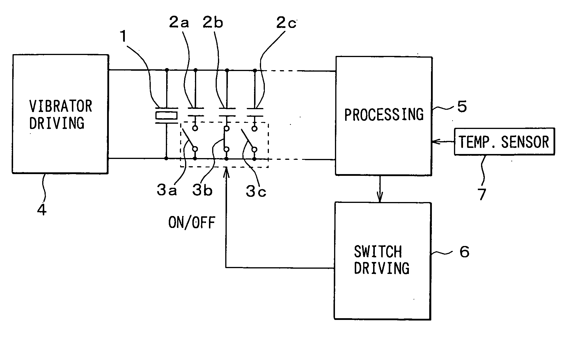
[0025] The ultrasonic sensor includes the piezoelectric vibrator 1, multiple capacitors 2a, 2b and 2c as capacitive components, multiple switches 3a, 3b and 3c, a vibrator driving circuit 4, an output signal processing circuit 5 and a switch driving circuit 6.

[0026] The piezoelectric vibrator 1 is attached to a housing (not shown). The piezoelectric vibrator 1 vibrates to transmit an ultrasonic wave and receives a reflected wave from an obstacle. An output signal corresponding to ...

second embodiment

[0046] As shown in FIG. 4, an ultrasonic sensor according to the second embodiment is different from that of the first embodiment in the following point. That is, a temperature sensor 7 is provided in order to estimate a temperature of the ultrasonic sensor. A temperature output signal from the temperature sensor 7 is inputted to the output signal processing circuit 5.

[0047] A position where the temperature sensor 7 is mounted is not limited particularly. However, it is required that a temperature in the position where the temperature sensor 7 is mounted correlates with a temperature in a position where the ultrasonic sensor is mounted. That is, it is preferable that the temperature sensor 7 is mounted near the ultrasonic sensor.

[0048] In the second embodiment, the output signal processing circuit 5 stores a switch control characteristic for temperature compensation in advance. The switch control characteristic for temperature compensation is a relationship between the estimated tem...

third embodiment

[0051] As shown in FIG. 5, an ultrasonic sensor according to the third embodiment has multiple coils 8a-8c instead of the multiple capacitors 2a-2c in the above embodiments. Similarly to the above embodiments, the coils 8a-8c can also compensate for electric capacity of the piezoelectric vibrator 1.


PUM


Abstract

An ultrasonic sensor includes a piezoelectric vibrator, a reverberation measuring device and a compensating device. The piezoelectric vibrator vibrates to transmit an ultrasonic wave, receives a reflected wave of the transmitted ultrasonic wave and produces an output signal corresponding to vibration of the piezoelectric vibrator. The reverberation measuring device measures a reverberation period of the piezoelectric vibrator from the output signal. The compensating device compensates for an operation characteristic of the piezoelectric vibrator in accordance with the measured reverberation period. Thus, the ultrasonic sensor can decrease a reverberation period, which may cause reduction in detection accuracy and impossibility of detection of an obstacle at a short distance.

Description

[0001] This application is based on Japanese Patent Application No. 2003-138406 filed on May 16, 2003, the disclosure of which is incorporated herein by reference.[0002] 1. Field of the Invention[0003] The present invention relates to an ultrasonic sensor which is used for a vehicle and the like.[0004] 2. Description of Related Art[0005] An ultrasonic sensor is used as an obstacle detection sensor for detecting obstacle by transmitting and receiving an ultrasonic wave. This ultrasonic sensor has a piezoelectric vibrator. The piezoelectric vibrator vibrates to transmit an ultrasonic wave and receives a reflected wave from an obstacle, so that an obstacle can be detected.[0006] However, the above ultrasonic sensor has a disadvantage that a reverberation occurs after normal vibration of the piezoelectric vibrator. Therefore, detection accuracy of the sensor may be reduced and the ultrasonic sensor may not be able to detect an obstacle at a short distance if the reverberation continues ...

Claims


Application Information

Patent Timeline
IPC IPC(8): B06B1/02G01S7/52G01S7/526B60R21/00G01S15/93H04R3/00H04R17/00
CPCB06B1/0215G01S7/52006Y10S367/901Y10S367/903G01S7/52
Inventor ODA, KIYONARIMAEDA, MANABUMATSUOKA, HISANAGASATO, YOSHIHISATAKEICHI, MASAKAZU
Owner DENSO CORP
Why Eureka
Try Eureka