Turboprop carrier structure and an assembly including such a carrier structure

a technology of a carrier structure and a turboprop is applied in the direction of machine/engine, machine support, power plant inspection panel, etc., which can solve the problems of affecting the performance of the mounting device, the inability to mount and dismount the engine, and the inability to meet the needs of the engine mounting and disassembly, etc., to achieve the effect of simple, reliable and relatively quick

Active Publication Date: 2004-11-18
SN DETUDE & DE CONSTR DE MOTEURS DAVIATION S N E C M A
View PDF5 Cites 32 Cited by
  • Summary
  • Abstract
  • Description
  • Claims
  • Application Information

AI Technical Summary

Benefits of technology

[0009] An object of the present invention is to provide a carrier structure enabling the various forces to which it is subjected to be withstood while also enabling the engine to be dismounted and remounted in a manner that is simple, reliable, and relatively quick. In particular, it is desired to provide a carrier structure that does not need to be fully dismounted in order to gain access to the engine during maintenance operations and / or in order to remove the engine.
[0015] In this manner, it will be understood that the presence of a top portion and a bottom portion made by means of structural elements (arches, beams, longerons, . . . ), a carrier structure is obtained that presents good strength, for weight that is not excessive.
[0016] In addition, mounting and dismounting the bottom portion is made easier by using the centering and fixing means, thus making access to the housing and thus to the turboprop easier.
[0018] Preferably, said top portion further comprises at least one intermediate arch mounted on said longitudinal beams between said front arch and said rear arch, likewise in order to reinforce the rigidity of the top portion.
[0023] Such an arrangement makes it possible for mounting between the top and bottom portions to be quick and simple.

Problems solved by technology

Proposals have also been made to provide a carrier structure in the form of a right portion and a left portion: nevertheless, that solution is ill-suited when it comes to mounting and dismounting the engine.
Furthermore, in the solutions that have been proposed in the past, in order to dismount the engine, or even in order to gain access to certain members of the engine, it has often been necessary to decouple the carrier structure from the airplane wing, at least in part, thereby making said operation relatively lengthy to perform.
Nevertheless, that mounting device presents a certain number of drawbacks.
In particular, no support structure is provided forming a structural assembly having strength and cohesion in a radial direction.

Method used


Image

  • Turboprop carrier structure and an assembly including such a carrier structure
  • Turboprop carrier structure and an assembly including such a carrier structure
  • Turboprop carrier structure and an assembly including such a carrier structure

Examples


Embodiment Construction

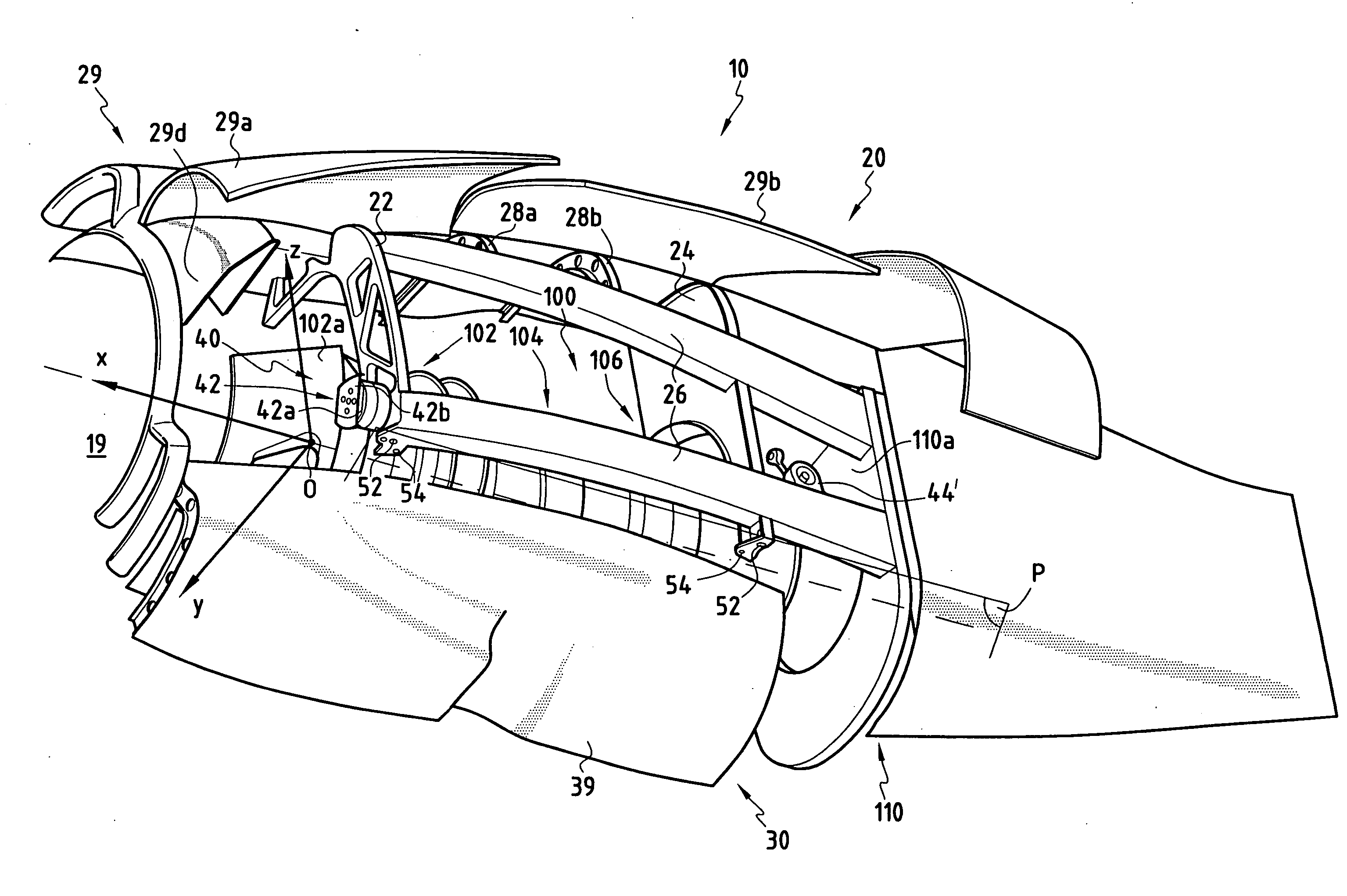
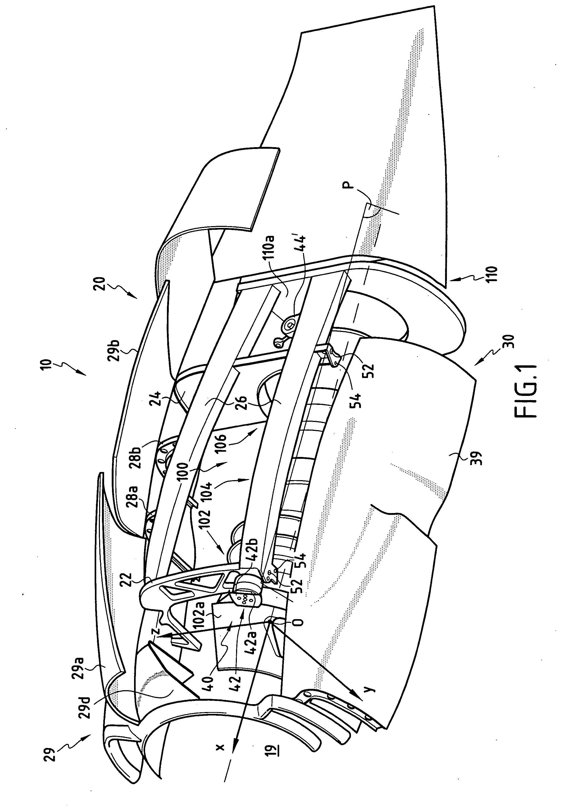
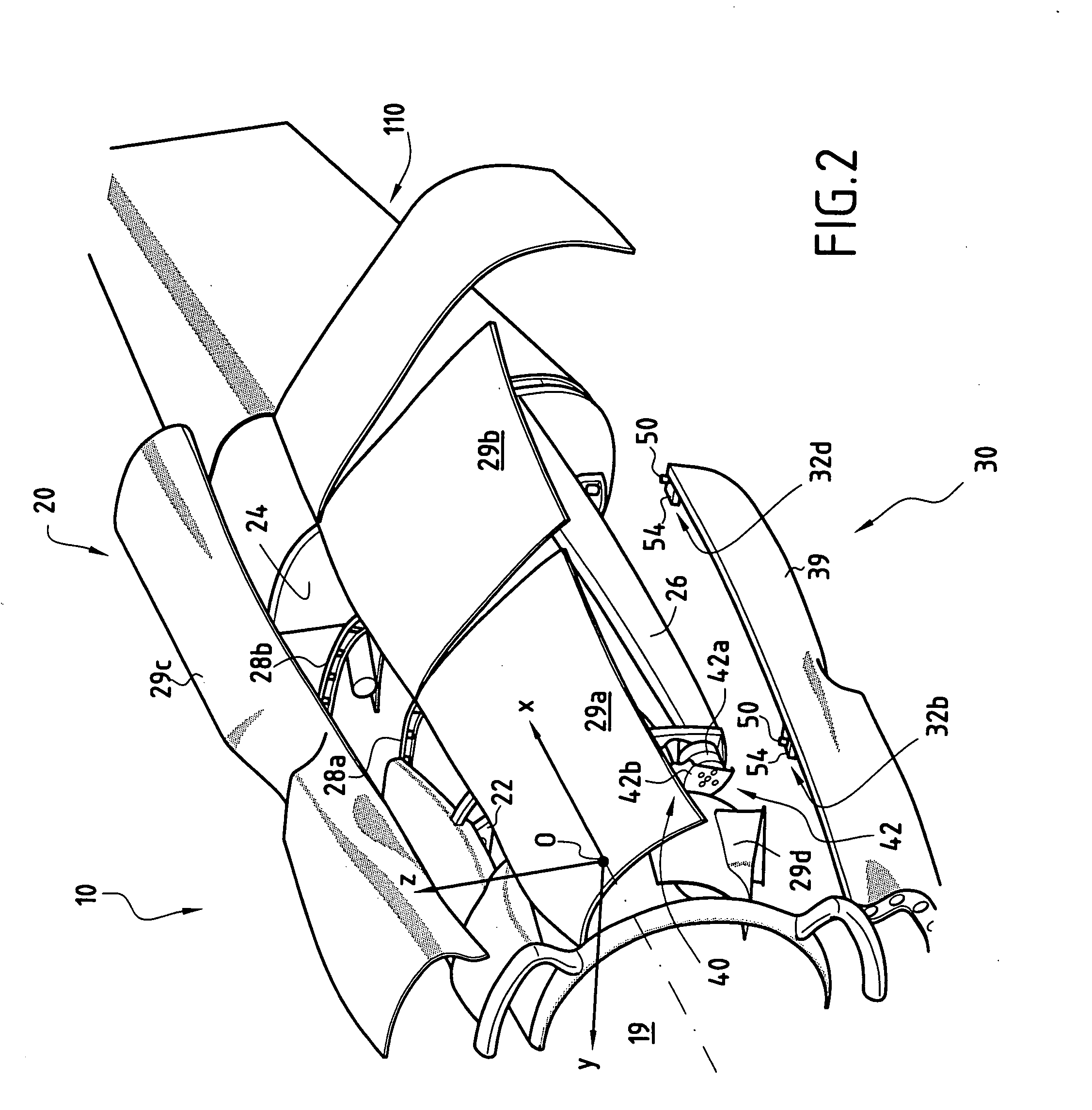
[0041] Reference is made initially to FIG. 1 in which the carrier structure 10 is shown in part as seen from the outside.

[0042] FIG. 1 also shows part of a turboprop 100 comprising a front portion 102, a central portion 104 and a rear portion 106. In conventional manner, the front portion 102 contains the fan 102a, the central portion 104 contains the compressor and the combustion chamber (not shown), and the rear portion 106 contains a turbine.

[0043] The way in which the turboprop 100 is mounted and dismounted on the carrier structure 10 is explained below after describing the various elements making up the carrier structure 10.

[0044] FIG. 1 also shows a portion of an airplane wing beneath which said load-carrier structure 10 is positioned.

[0045] More precisely, FIG. 1 shows a portion of the wing framework 110 in the form of a yoke 110a forming a support frame for the carrier structure 10.

[0046] The wing (not shown) extends in a generally transverse direction (Oy), while the carrie...


PUM


Abstract

The carrier structure of the invention is used for carrying a turboprop and it is designed to be mounted beneath and / or in front of an airplane wing. In characteristic manner, said carrier structure comprises: a top portion comprising a front arch, a rear arch, and longitudinal beams; an upwardly-open removable bottom portion comprising at least two bottom arches and longerons; said bottom portion being demountably fixed to the top portion by centering and fixing means, said bottom and top portions together defining a housing suitable for receiving said turboprop, and a suspension for carrying said turboprop.

Description

[0001] The invention relates to a carrier structure for a turboprop, the turboprop having a front portion comprising a fan, a central portion, and a rear portion, and being designed to be mounted in a longitudinal direction beneath and / or in front of an airplane wing, said wing having a framework.[0002] It should be understood that although the present invention is particularly adapted to a turboprop, i.e. to a jet engine whose turbine drives an external propeller, it may also be applied to other types of jet engine.[0003] The present invention also relates to making an assembly comprising a carrier structure as mentioned above, an airplane wing to which said structure is fixed, and a turboprop.[0004] Such a carrier structure must naturally enable the engine to be supported both when at rest and when in operation. In particular, it is necessary for the carrier structure to withstand the thrust forces from the engine, which forces must also be properly transferred to the framework of...

Claims


Application Information

Patent Timeline
Patent Type & Authority Applications(United States)
IPC IPC(8): B64D27/26B64D27/12B64D27/16B64D29/02B64D29/06B64D29/08
CPCB64D27/12B64D29/02B64D29/06B64D29/08
Inventor PICARD, JEAN-LOUISMAZEAUD, GEORGES
Owner SN DETUDE & DE CONSTR DE MOTEURS DAVIATION S N E C M A
Why Eureka
Try Eureka