Circuit in light emitting display

a technology of light-emitting display and circuit, applied in the field of electroluminescence, can solve the problems of difficult display with a large number of pixels and gradations, and the accuracy of written data in the indirect specification system is inferior to the direct specification system

Active Publication Date: 2004-11-25
SANYO ELECTRIC CO LTD
View PDF15 Cites 46 Cited by
  • Summary
  • Abstract
  • Description
  • Claims
  • Application Information

AI Technical Summary

Problems solved by technology

Therefore, in a direct specification system, there had been a problem in that a display with a large number of pixels and a large number of gradations was difficult.
However, as described above, the indirect specification system is inferior to the direct specification system in the precision of written data.

Method used


Image

  • Circuit in light emitting display
  • Circuit in light emitting display
  • Circuit in light emitting display

Examples


Embodiment Construction

[0044] A preferred embodiment of the present invention will now be described referring to the drawings.

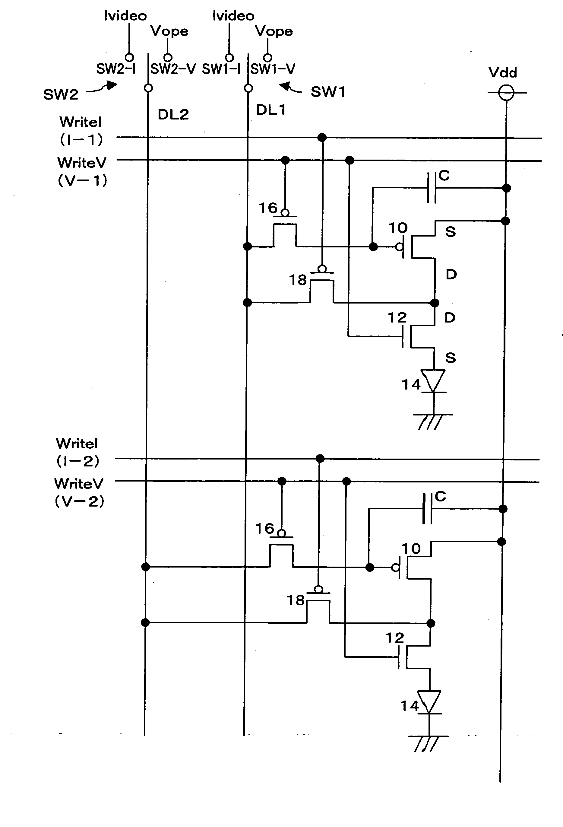
[0045] FIG. 3 is a diagram showing a structure of the preferred embodiment. A source (source region) of a p-channel TFT 10 is connected to a power supply Vdd and a drain (drain region) of the p-channel TFT 10 is connected to an anode of an organic EL element 14 via an n-channel TFT 12. A cathode of the organic EL element 14 is connected to a ground.

[0046] A gate of the TFT 10 is connected to a data line DL (DL1 or DL2) through a p-channel TFT 16 and is also connected to a power supply line Vdd via a storage capacitor C. A connection point between the TFT 10 and the TFT 12 is connected to the data line DL via the TFT 18.

[0047] A write line WriteI which extends along the row direction is connected to a gate of the TFT 18 and a write line WriteV which also extends along the row direction is connected to gates of the TFTs 12 and 16.

[0048] In the present embodiment, as the data line DL,...


PUM


Abstract

A light emitting display having an emissive element which emits light in response to a supplied current, comprises a drive current generating element for generating a drive current for allowing light to be emitted from the emissive element, a data line onto which a voltage signal and a current signal corresponding to data regarding an amount of light emission from the emissive element are sequentially supplied, and a voltage storage element connected to the data line and for sequentially storing a charge voltage based on the voltage signal and the current signal corresponding to data regarding the amount of light emission. The drive current generated by the drive current generating element based on a charge voltage corresponding to the current signal stored in the voltage storage element is supplied to the emissive element so that generation of precise drive current corresponding to data regarding the amount of light emission is enabled and the time required for writing data into the voltage storage element is shortened.

Description

[0001] 1. Field of the Invention[0002] The present invention relates to an electroluminescence (hereinafter simply referred to as "EL") display circuit for controlling light emission from an EL element based on both a data voltage and data current generated based on data for driving the EL element.[0003] 2. Description of the Prior Art[0004] Because EL display devices in which a self-emitting EL element is used as an emissive element in each pixel have advantages such as that the device is thin, self-emitting, and consumes less power, EL display devices have attracted much attention as alternatives to display devices such as liquid crystal display (LCD) and cathode ray tube (CRT) display devices.[0005] In particular, a high resolution display can be achieved by an active matrix EL display device in which a switching element such as a thin film transistor (hereinafter simply referred to as "TFT") for individually controlling an EL element is provided in each pixel and the EL element ...

Claims


Application Information

Patent Timeline
Patent Type & Authority Applications(United States)
IPC IPC(8): G09F9/30H01L51/50G09G3/00G09G3/20G09G3/30G09G3/32H01J1/304H01L27/32H05B33/00H05B33/14H05B44/00
CPCG09G3/3266G09G3/3283G09G3/3291G09G2320/0233G09G2300/0861G09G2310/0251G09G2300/0814E02B3/129
Inventor MATSUMOTO, SHOICHIRO
Owner SANYO ELECTRIC CO LTD
Why Eureka
Try Eureka