
System and method for constraining a graphical hand from penetrating simulated graphical objects

a graphical object and graphical hand technology, applied in the field of system and method for constraining a graphical hand from penetrating simulated graphical objects, can solve the problems of limited degree of freedom of movement of the device, lagged software for whole-hand input interfaces, and complex modeling of computer-generated environments

Inactive Publication Date: 2004-11-25
IMMERSION CORPORATION
View PDF99 Cites 62 Cited by
  • Summary
  • Abstract
  • Description
  • Claims
  • Application Information

AI Technical Summary

Problems solved by technology

This is not surprising considering the complexity involved in physically modeling computer-generated environments.
In these cases, either the degrees of freedom of movement of the device are limited, or a single point is interacting with the environment.
Not surprisingly, comparable software for whole-hand input interfaces has lagged behind because of the inherent complexity of the whole-hand interaction paradigm, with its multiple constraints and multiple, articulated degrees of freedom.
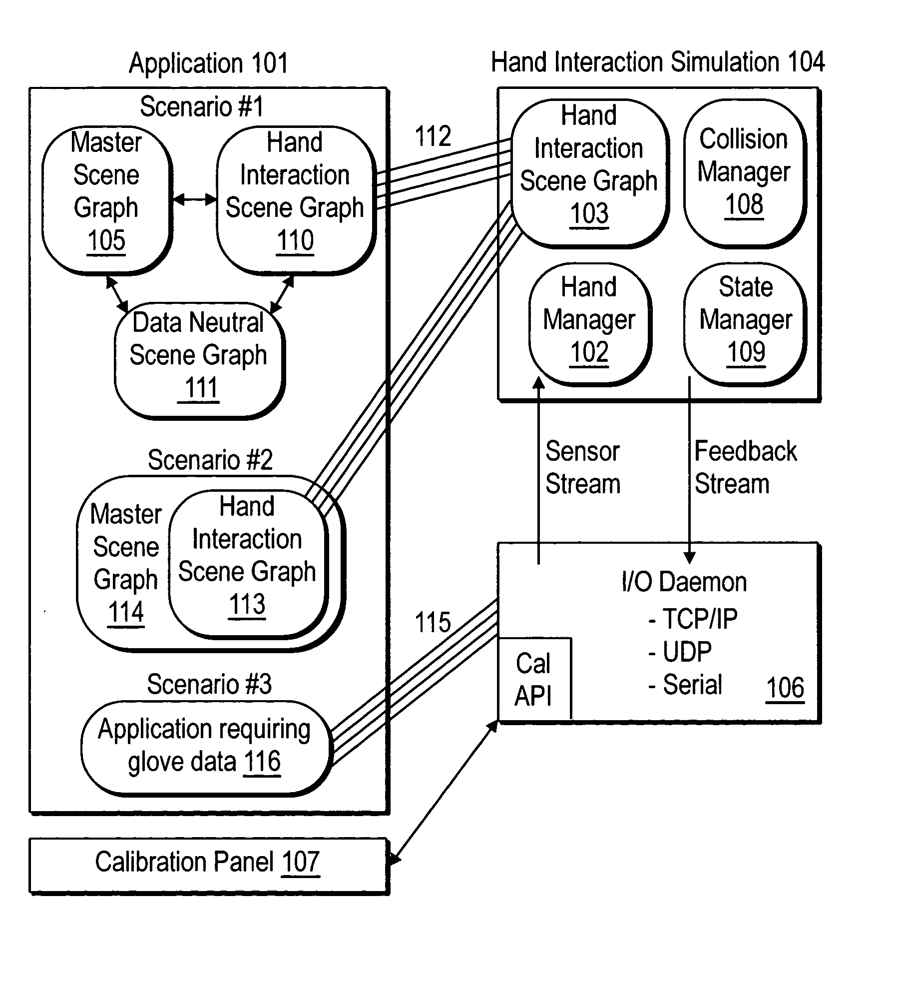
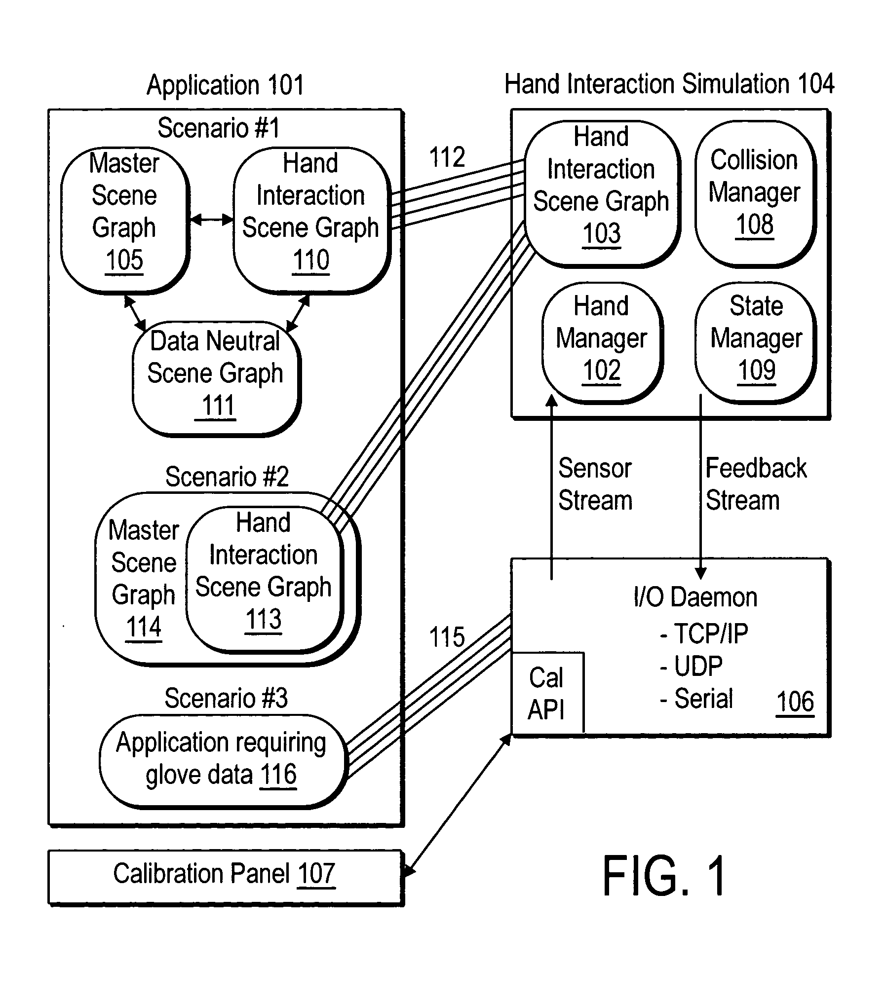
Both let the user display a graphical hand on the screen that mimics the glove wearer's movement, but they do not provide manipulation capabilities; such capabilities are presently left to the user to develop.

Method used


Image

  • System and method for constraining a graphical hand from penetrating simulated graphical objects
  • System and method for constraining a graphical hand from penetrating simulated graphical objects
  • System and method for constraining a graphical hand from penetrating simulated graphical objects

Examples


embodiment

[0086] Embodiment

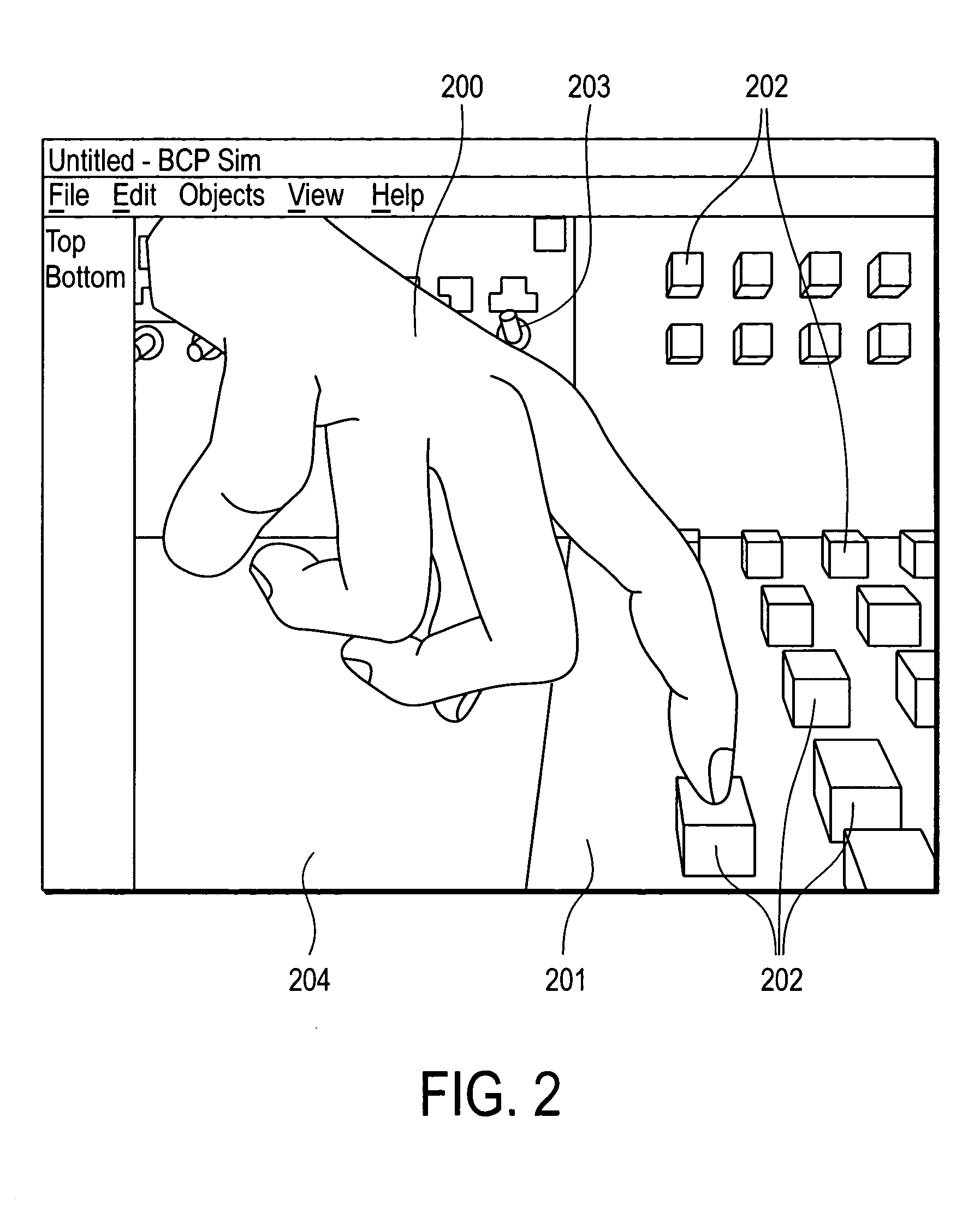
[0087] An embodiment which illustrates the functionality of the VirtualHand Toolkit consists of a simulation of a virtual control panel (FIG. 2). The user may interact with the control panel and buttons using a CyberGlove instrumented glove, and optionally with a CyberGrasp force-feedback device. The control panel contains grounded objects and surfaces, in addition to push buttons and toggle switches. When the CyberGrasp force-feedback device is used, the user can also feel the resistance of the buttons being pressed.

[0088] FIG. 4 is a link-revolute-joint model of the human hand (400). The forearm link (401) is connected to the wrist yaw joint (402) which is connected to the wrist pitch joint (403). This joint is connected to the metacarpus link (404) which extends to connect to the thumb roll joint (405). This joint is connected to the thumb abduction joint (406) which is connected by the thumb metacarpal link (407) to the thumb metacarpal roll joint (408). This jo...


PUM


Abstract

An apparatus, system, method, and computer program and computer program product are provided for constraining the movement of a graphical hand when the physical hand controlling the graphical hand does not have a similar physical constraint. The constraining technique may comprise use and analysis of a revolute-joint-link-spring model. In such a model, an uncompressed / unextended spring position represents the corresponding measured joint angle or link position. In addition to linear springs which follow Hook's Law, i.e., F=k*x, non-linear springs or other non-linear force functions may be employed to obtain the desired result of allowing a graphical joint or link to deviate from what the corresponding measured joint or link provides. In particular, if a graphical hand configuration corresponding to measured joint and link positions causes a portion of the hand to penetrate a simulated graphical solid object, a mathematical determination is used to compute modified joint and link positions such that the graphical hand part will no longer penetrate the graphical solid object. Such a constraint technique may include solving a spring model such that the various joint and link springs compress or extend to produce modified joint and link positions. Such a constraint technique may also be applied to constrain other graphical body parts and graphical inanimate objects, where corresponding physical controlling, i.e., measured, body parts and inanimate objects do not possess a similar constraint or impediment.

Description

[0001] This application claims the benefit of priority to Provisional Application Ser. No. 60 / 106,904, filed 3 Nov. 1998, which is hereby incorporated by reference. This application also claims the benefit of priority to U.S. patent application Ser. No. 09 / 076,617 filed 12 May 1998, which itself incorporates by reference and claims the benefit of priority to U.S. Provisional Application Ser. No. 60 / 046,185, filed 12 May 1997, each of which are hereby incorporated by reference.[0002] This invention relates generally to systems, apparatuses, and methods for simulation and training using interactive computer graphics.[0003] Description of the Relevant Art[0004] In the past few years, computers have seen a significant increase in 3D graphical capabilities. Not surprisingly, interfaces capable of interacting with these complex 3D environments have started to move from laboratories to the enterprise and the consumer market as companies have begun to produce them in volume. While interfaci...

Claims


Application Information

Patent Timeline
IPC IPC(8): G06F17/50
CPCG06T19/20G06T2210/21G06T2210/28G06T2219/2016G06T2219/2021G06F3/011
Inventor KRAMER, JAMES F.ULLRICH, CHRISTOPHER
Owner IMMERSION CORPORATION
Learn More