Motor with a brake

a technology of brakes and motors, applied in the direction of motor/generator/converter stoppers, dynamo-electric converter control, forging/pressing/hammering apparatus, etc., can solve the problem of difficult to apply excessive load not only to the brakes, but also to the motor itsel

Inactive Publication Date: 2004-12-02
TAMAGAWA SEIKI CO LTD
View PDF1 Cites 24 Cited by
  • Summary
  • Abstract
  • Description
  • Claims
  • Application Information

AI Technical Summary

Problems solved by technology

Thus, when the motor is driven for a long period of time, voltage of an initial level continues to be applied to the brake all the while, and the brake generates heat, which is transmitted to the stator side, making it difficult to apply excessive load not only to the brake but also to the motor itself.

Method used


Image

  • Motor with a brake
  • Motor with a brake
  • Motor with a brake

Examples


Embodiment Construction

[0016] A motor with a brake according to a preferred embodiment of the present invention is hereinafter described with reference to the drawings.

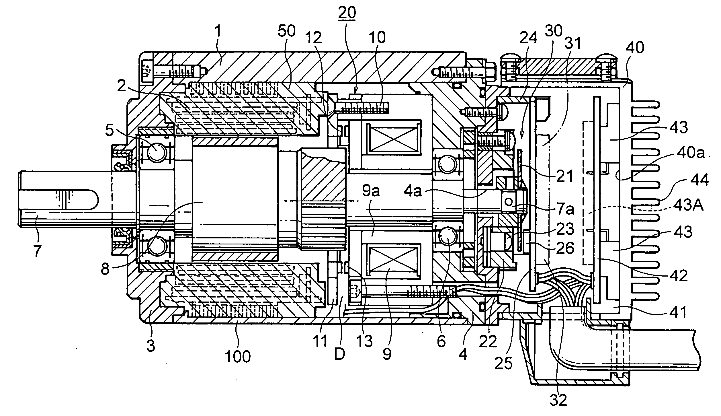
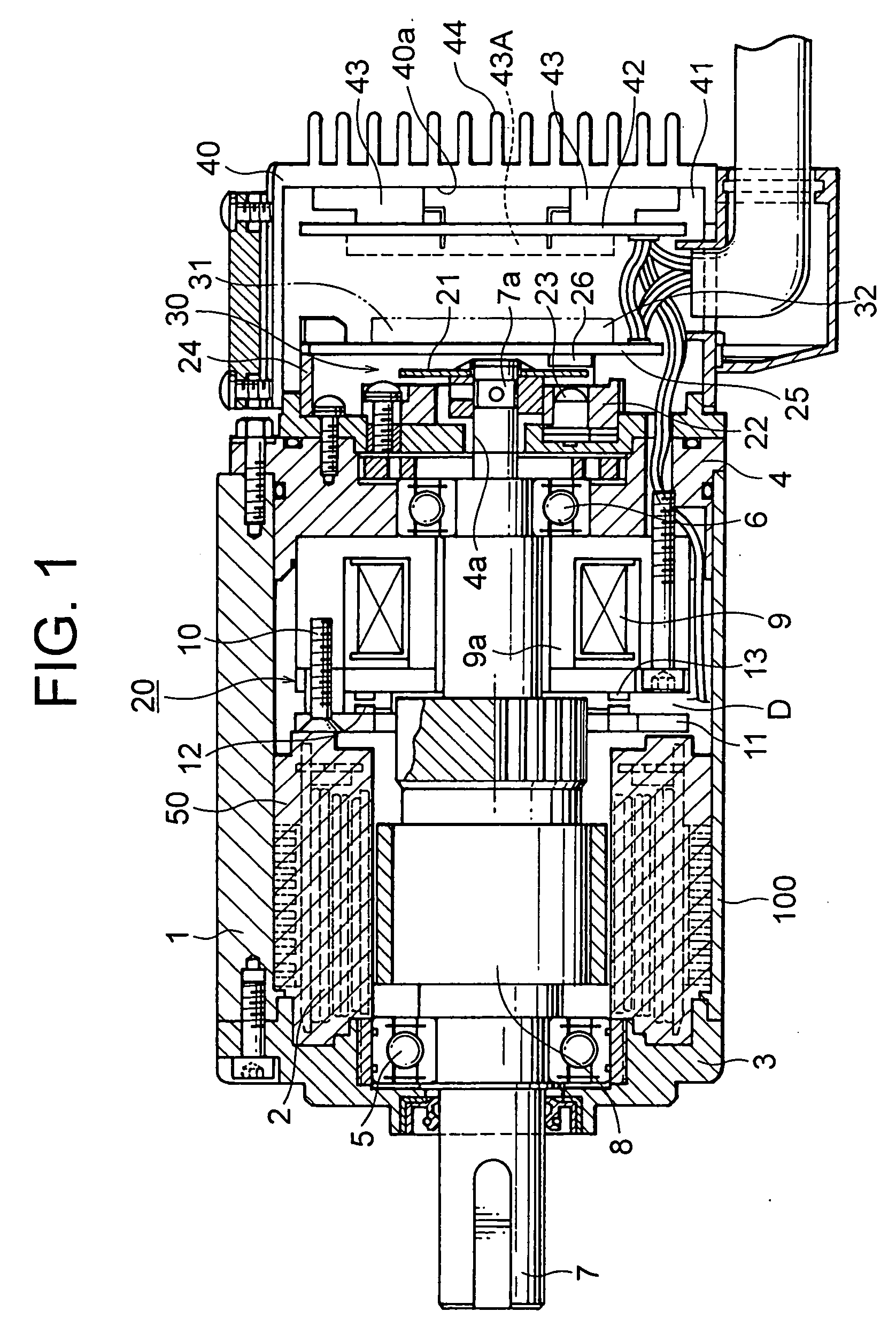
[0017] In FIG. 1, numeral 1 indicates a cylindrical case having a stator 3 around which a stator coil 2 is wound. A front cover 3A and a rear cover 4 are mounted respectively to the ends of the cylindrical case 1.

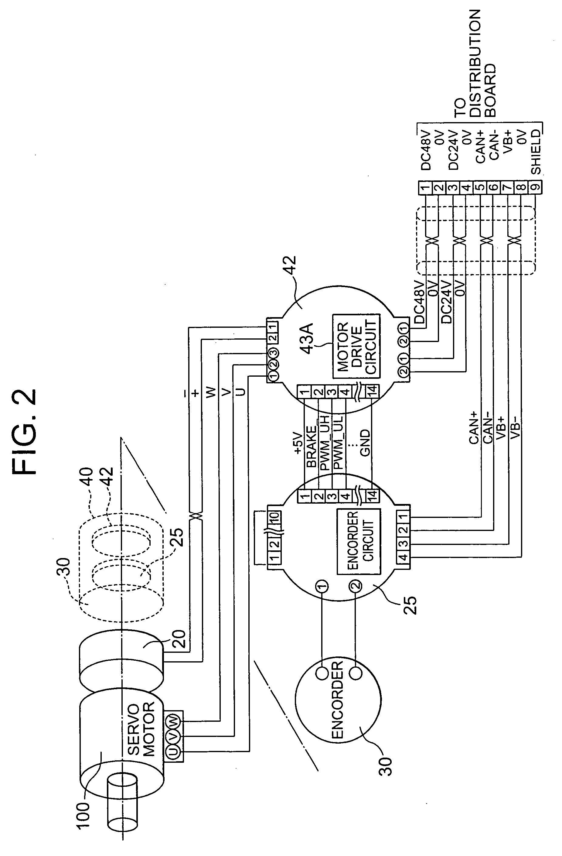
[0018] A rotation shaft 7 is rotatably supported by bearings 5 and 6 provided in the front cover 3A and the rear cover 4, respectively. A rotor 8 situated inside the stator 3 is rotatably provided on the rotation shaft 7, and the rear cover 4 is equipped with an electromagnetic drive portion 9 having an excitation coil (not shown). The stator 3, the rotor 8, and an encoder 30 constitute a servo motor portion 100.

[0019] A stationary plate 11 is secured to a position on the front cover 3A side of the electromagnetic drive portion 9 through the intermediation of a bolt 10 so as to maintain a gap D therebetween.

[0020] Arranged inside t...


PUM

PropertyMeasurementUnit
voltageaaaaaaaaaa
voltageaaaaaaaaaa
voltageaaaaaaaaaa

Abstract

The present invention provides a motor with a brake in which, after an initial stage, a voltage applied to the brake is reduced to thereby restrain heat generation in the brake. In the motor with a brake, after signal drive, a voltage of a drive signal supplied to an electromagnetic drive portion of the brake is reduced, whereby heat generation in the brake during motor rotation is restrained, which makes it possible to increase a load to be applied to the motor.

Description

[0001] 1. Field of the Invention[0002] The present invention relates to a motor with a brake. In particular, the present invention relates to a novel improvement of a motor with a brake for restraining heat generation in a coil of an electromagnetic drive portion of the brake. The restrain of heat generation can be attained such that a normal voltage is applied during initial excitation for brake releasing with a motor drive power on and in which, after initial excitation, a lower voltage is applied for excitation.[0003] 2. Description of the Related Art[0004] In a conventional motor with a brake of this type, the electromagnetic drive portion is on when the motor is on to keep the brake electromagnetically released. When the motor is turned off, the brake is engaged by a spring, preventing rotation of the rotor by the brake (see, for example, JP 2000-50569 A).[0005] The conventional motor with a brake is constructed as described above, and therefore has the following problems.[0006...

Claims


Application Information

Patent Timeline
Patent Type & Authority Applications(United States)
IPC IPC(8): H02K7/102H02K11/04H02P3/04
CPCH02K7/1025H02K11/0073H02P3/04H02K11/33B21J7/22B21J13/02B21J13/085
Inventor MIURA, HIROMASANODA, TOSHIYUKI
Owner TAMAGAWA SEIKI CO LTD
Why Eureka
Try Eureka