
Image processing system, projector, program, information storage medium and image processing method

a technology of image processing and projector, applied in the field of image processing system, projector, program, information storage medium and image processing method, can solve the problems of image deterioration, loss of original display effect, and non-uniformity from luminance non-uniformity

Inactive Publication Date: 2004-12-02
SEIKO EPSON CORP
View PDF13 Cites 20 Cited by
  • Summary
  • Abstract
  • Description
  • Claims
  • Application Information

AI Technical Summary

Benefits of technology

[0008] The present invention is made in view of the above-mentioned problem and its object is to provide an image processing system, projector, program, information storage medium and image processing method which can cause the coordinates of the sensed projected image in the sensing area to be precisely associated with the coordinates of the spatial light modulator.
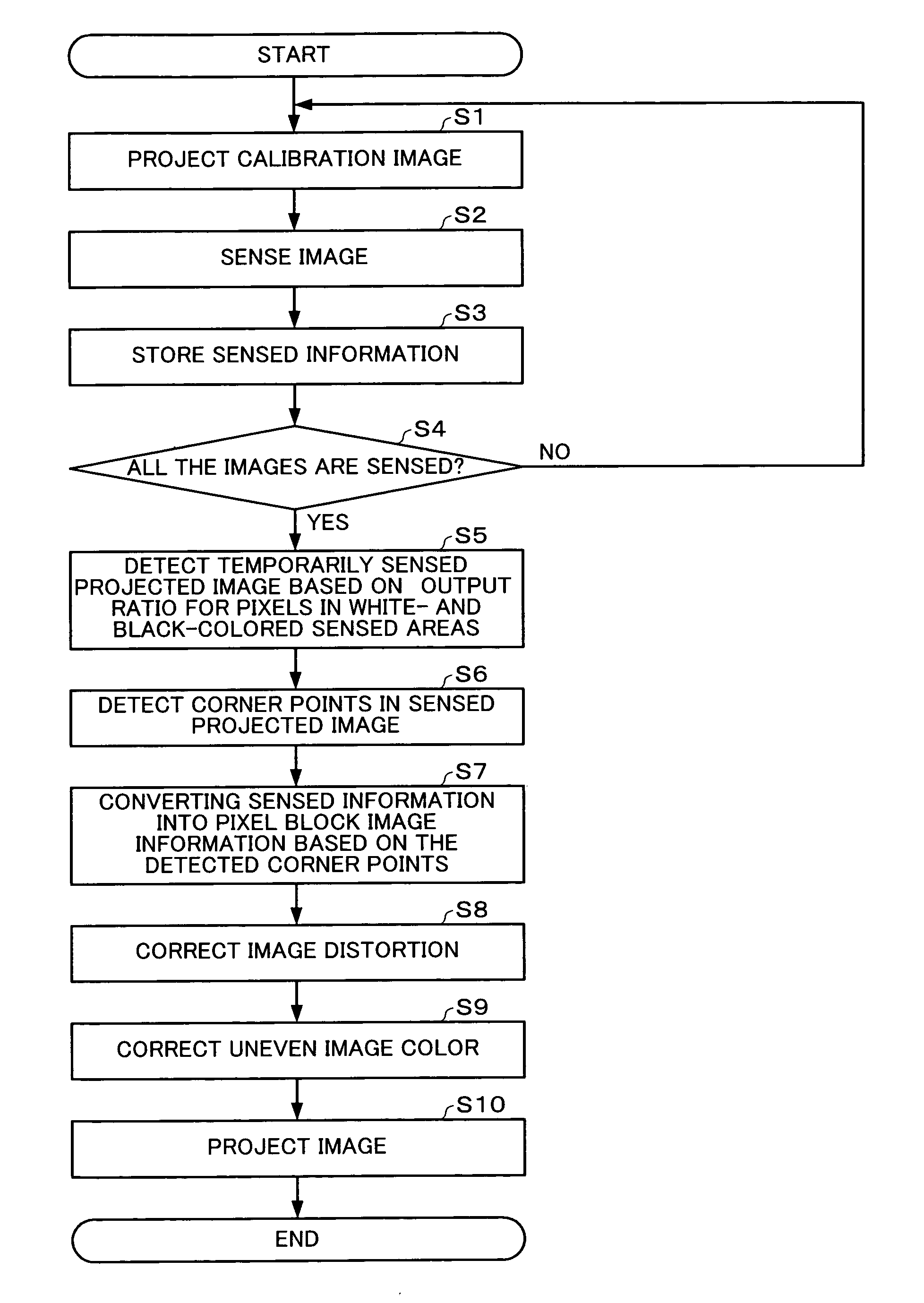
[0066] The image processing system and others of the present invention can more precisely and effectively detect edge points in a sensed projected image than the conventional technique of detecting edge points through filtering, by using ratio information provided when the ratio of image signal values or luminance values of the associated pixels in the sensing area is computed. Thus, the image processing system and others can cause the coordinates of the sensed projected image in the sensing area to be precisely associated with the coordinates of the spatial light modulator.
[0067] The image processing system and others can more effectively perform the image processing because they use the ratio rather than the differential value and do not require any change of the first predetermined value which is a determination criterion for edge points in the sensed projected image.
[0074] Thus, when an ordinary rectangular image is projected, the image processing system and others can precisely and effectively detect the four corner points in the sensed projected image by simply detecting a temporary sensed projected image and then detecting an actual sensed projected image based on the temporary sensed projected image.
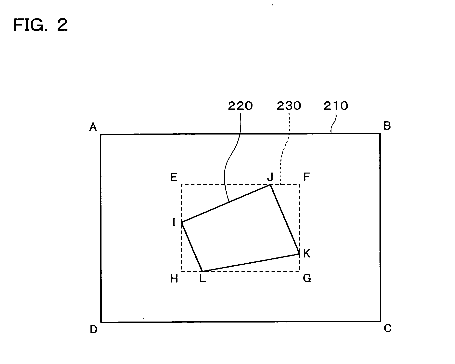
[0087] Thus, the image processing system and others can detects correct corner points through different searching methods even if only three or less corner points are detected in detecting four corner points in the sensed projected image. Thus, even if the image is distorted into various different shapes, the image processing system and others can precisely and effectively detect the four corner points in the sensed projected image. Therefore, the coordinates of the sensed projected image in the sensing area can precisely be associated with the coordinates of the spatial light modulator.
[0090] Since the image processing system and others can precisely detect the sensed projected image in the sensing area, they can precisely correct the distortion and color non-uniformity in the image for each pixel block even if the sensed projected image is divided into pixel blocks for correcting image signals. In such a manner, a correct image can be displayed.

Problems solved by technology

If an image is displayed in an image display device such as a projector for a long term, the image will gradually deteriorate due to color non-uniformity occurred therein (including color non-uniformity from luminance non-uniformity).
In such a case, an original display effect may be lost by color non-uniformity occurred in the image due to deterioration of a liquid crystal panel or polarizing plate from the long-term projection of the image.
However, Japanese Patent Laid-Open No. 2002-140060 does not particularly describe a technique for causing the coordinates of the sensed projected image in the sensing area to be precisely associated with the coordinates of the spatial light modulator.

Method used


Image

  • Image processing system, projector, program, information storage medium and image processing method
  • Image processing system, projector, program, information storage medium and image processing method
  • Image processing system, projector, program, information storage medium and image processing method

Examples


Embodiment Construction

[0098] The present invention will now be described in connection with a projector having an image processing system with reference to the drawing. It is to be understood that an embodiment shown in the following is not intended to limit the subject matter of the invention as described in the accompanying claims and that all the components shown in such an embodiment is not necessarily essential for practicing the invention defined by the accompanying claims.

[0099] The Whole System

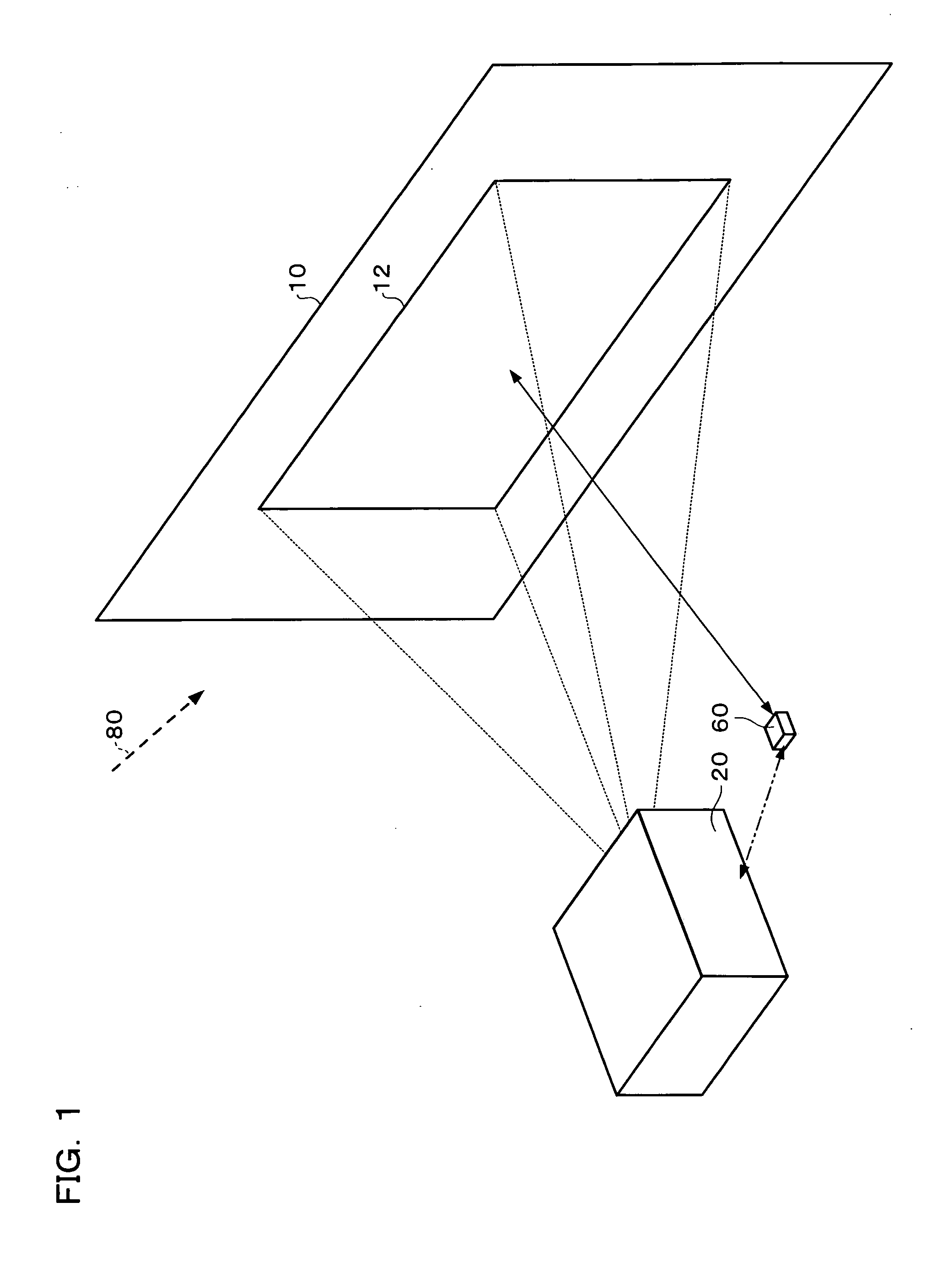
[0100] FIG. 1 is a diagram schematically showing an image projected according to one embodiment of the present invention.

[0101] A projector 20 projects an image onto a screen 10. Thus, a projected image 12 is formed on the screen 10.

[0102] When an image is continuously displayed through a projection type image display device such as the projector 20 for a long term, color non-uniformity (including color non-uniformity due to luminance non-uniformity) will gradually occur in the projected image 12 due time d...


PUM


Abstract

To provide an image processing system enabling association of the coordinates of a sensed projected image in a sensing area with the coordinates of the spatial light modulator, a projector is formed of: an image projecting section which projects calibration images; a ratio information generating section which computes a ratio of image signal values or luminance values for each pixel in the sensing area obtained by sensing the calibration images, based on sensed information from a sensor which senses the calibration images, to generate ratio information; an edge point detecting section which searches the ratio information to detect corner points of a sensed projected image for each pixel having a ratio equal to or larger than a predetermined value; a pixel block image information generating section which converts sensed information of an area defined by the detected corner points into pixel block image information representing a ratio of image signal values or luminance values for each pixel block including one or more pixels.

Description

[0001] Japanese Patent Application No. 2003-91720, filed on Mar. 28, 2003 is hereby incorporated by reference in its entirety.BACKGROUD OF THE INVENTION[0002] The present invention relates to an image processing system, projector, program, information storage medium and image processing method which can detect a sensed projected image based on sensed information.[0003] If an image is displayed in an image display device such as a projector for a long term, the image will gradually deteriorate due to color non-uniformity occurred therein (including color non-uniformity from luminance non-uniformity).[0004] For example, in a store or exhibition ground, an image may continuously be displayed on a screen through a projector for a long term. In such a case, an original display effect may be lost by color non-uniformity occurred in the image due to deterioration of a liquid crystal panel or polarizing plate from the long-term projection of the image.[0005] In view of such a problem, for e...

Claims


Application Information

Patent Timeline
Patent Type & Authority Applications(United States)
IPC IPC(8): G03B21/00G03B21/14G06K9/40G06T3/00G06T5/00G09G5/00G09G5/02G09G5/06H04N1/40H04N5/74H04N9/31
CPCH04N9/3182H04N9/3197H04N9/3185E06B1/347
Inventor MATSUDA, HIDEKI
Owner SEIKO EPSON CORP
Learn More