
Oxidizer package for propellant system for rockets

a technology of propellant system and oxidizer, which is applied in the direction of explosives, etc., can solve the problems of compromising the theoretical performance potential, affecting the safety of handling and storage, and many of the oxidizers suffering from varying degrees and forms of instability

Inactive Publication Date: 2004-12-09
CESARONI ANTHONY JOSEPH +2
View PDF15 Cites 13 Cited by
  • Summary
  • Abstract
  • Description
  • Claims
  • Application Information

AI Technical Summary

Problems solved by technology

Traditionally, propulsion systems have used liquid oxidizers, which in many cases present handling and storage safety issues.
However, many of these oxidizers suffer from varying degrees and forms of instability, such as photo sensitivity, shock, friction and impact sensitivity, decomposition in the presence of moisture, sensitivity to pH and incompatibility (such as hypergolic reaction) to other propellant materials.
Many difficulties have been encountered incorporating the oxidizers into propellant systems, and solutions to particular storage and stability problems often result in compromising the theoretical performance potential.
This seriously impacts formulation rheology and can prevent achievement of optimum solids loading, as well as aggravating friction sensitivity during mixing and casting operations.
Some of the difficulties in these approaches include flow stability, concentration and distribution of oxidizer solids in carrier agents, pressurization and piping system requirements, specialized control valves and system integration.
Certain examples of flowable oxidizers can behave as mono-propellants causing flame tracking and catastrophic failure in the delivery and storage systems.

Method used


Image

  • Oxidizer package for propellant system for rockets
  • Oxidizer package for propellant system for rockets
  • Oxidizer package for propellant system for rockets

Examples


example ii

[0124] Samples of the grid in Example I were packaged in a paper / phenolic laminate tubular inhibitor sleeve and equipped with an initiator. The samples were successfully subjected to firing tests.

example iii

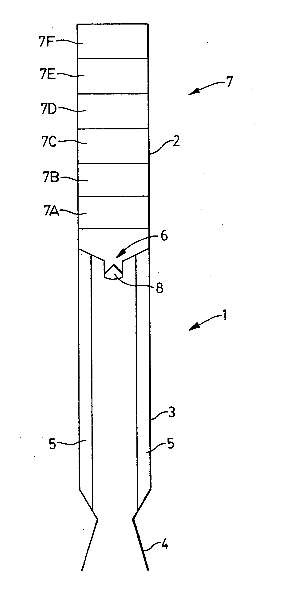
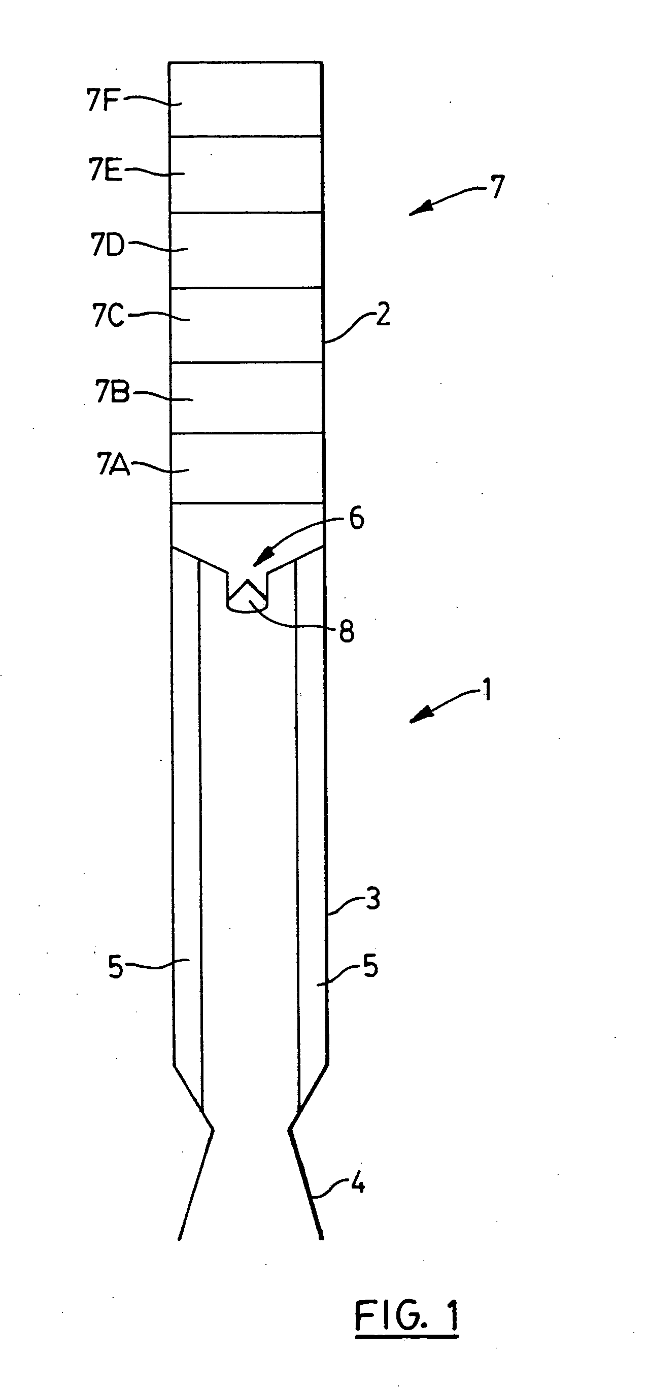
[0125] For testing of samples, a test solid propellant motor was fabricated in a modular form. The motor had a casing that was 2.5 inches (6.3 cm) in diameter and was capable of receiving one, two or three ancillary grains / packets of 1.025 inches (2.60 cm) in length. The motor was typically used with an inhibitor plate as disclosed herein, and appropriate end closures. The motor was similar in design to that of FIG. 1, except that it was intended for laboratory testing.

[0126] The motor was successfully loaded and fired with samples fabricated according to the procedure of Example I on numerous occasions.

example iv

[0127] A propellant composition was formulated as follows:

1 Wt % Ammonium perchlorate, spherical, 200 micron 56.0 Ammonium perchlorate, ground, 15 micron 21.6 GAP polyol 12.7 GAP plasticizer 5.6 Bonding agent 0.046 Antioxidant / metal deactivator 0.10 Diisocyanate curative 1.6 Superfine Iron oxide 0.25 Carbon black 0.050 Aluminum, spherical, 2 micron 2.0

[0128] A grain was formed using the above propellant, with GAP enclosed in ampoules imbedded in the propellant.

[0129] Characterization firings were performed in a 1.5 inch (3.8 cm) micro-motor using single Bates grain with approximately 50 g propellant mass. A burn rate of 1.5 inches / second was achieved at 500 psia chamber pressure.

[0130] This example illustrates use of ampoules in propellants. The formulation was not optimized.


PUM

PropertyMeasurementUnit
diameteraaaaaaaaaa
thicknessaaaaaaaaaa
lengthaaaaaaaaaa

Abstract

An oxidizer package for a propellant system for a motor in which the oxidizer is separated from fuel grain, the oxidizer package comprising oxidizer material and an ignition system therefor in a wrapping or sealing material. A hybrid rocket comprising oxidizer material and fuel grain, the oxidizer material being separated from the fuel grain and being in the form of a single package or plurality of packages of oxidizer material and an ignition system therefor, said packages generally conforming to the shape of the rocket. A grid of a pyrotechnic material. A propulsion system for a hybrid rocket comprising oxidizer material in a matrix, mesh, wool, foamed metal or wires of structural or pyrotechnic material.

Description

[0001] This application is a continuation of patent application Ser. No. 09 / 565,509, filed May 5, 2000, entitled "OXIDIZER PACKAGE FOR PROPELLANT SYSTEM FOR ROCKETS", which claims the benefit of U.S. provisional application Ser. No. 60 / 132,795, filed May 6, 1999, entitled "PROPELLANT SYSTEM FOR HYBRID ROCKETS", and U.S. provisional application Ser. No. 60 / 161,771, filed Oct. 27, 1999, entitled "OXIDIZER PACKAGE FOR PROPELLANT SYSTEM FOR ROCKETS".[0002] The present invention relates to a propellant system for a hybrid rocket. In particular, the propellant system utilizes discrete packages of oxidizer capable of being stored in the oxidizer section of the hybrid rocket. In embodiments, the present invention relates to an oxidizer package for a propellant system for a rocket, in which the package contains ampoules of compounds that enhance the performance of the propellant system. In particular, the ampoules contain oxidizer. The present invention also relates to a rocket utilizing oxi...

Claims


Application Information

Patent Timeline
Patent Type & Authority Applications(United States)
IPC IPC(8): C06B45/00C06B45/18
CPCC06B45/00C06B45/18
Inventor CESARONI, ANTHONY JOSEPHDENNETT, MICHAEL J.LOUWERS, JEROEN
Owner CESARONI ANTHONY JOSEPH
Learn More