
Dynamic testing device and dynamic testing method for burning speed of initiative laser type solid rocket propellant

A solid rocket, dynamic testing technology, applied in the use of devices that measure the time required to move a certain distance, radio wave measurement systems, chemical analysis using combustion, etc. The problems of inaccurate burning rate test of solid propellant have achieved the effect of high test accuracy and simple structure

Active Publication Date: 2017-01-25
UNIV OF SHANGHAI FOR SCI & TECH
View PDF9 Cites 8 Cited by
  • Summary
  • Abstract
  • Description
  • Claims
  • Application Information

AI Technical Summary

Problems solved by technology

However, under actual working conditions, the burning rate of the propellant will be affected by the pressure and change, and when the solid propellant burns, it usually produces a lot of smoke, which makes the light attenuation of the burning flame of the drug stick serious. Two photoelectric sensors Weakened received live radiation signal, resulting in inaccurate solid propellant burn rate tests

Method used

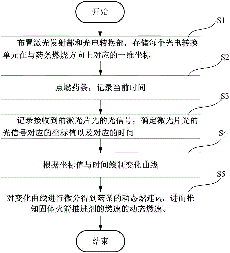
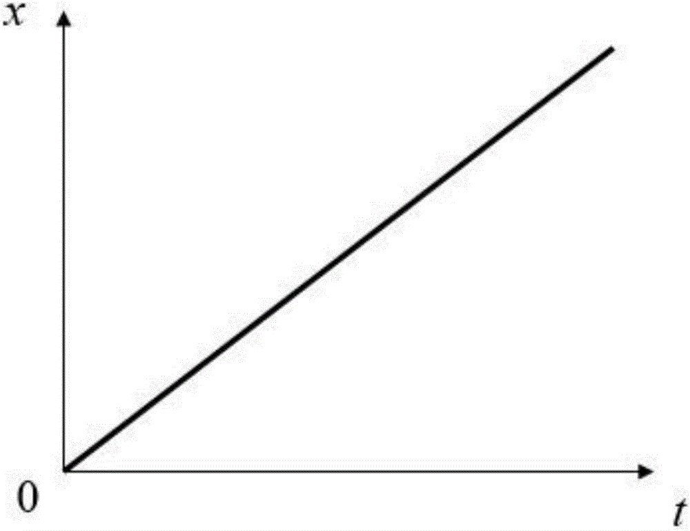

Image

  • Dynamic testing device and dynamic testing method for burning speed of initiative laser type solid rocket propellant
  • Dynamic testing device and dynamic testing method for burning speed of initiative laser type solid rocket propellant
  • Dynamic testing device and dynamic testing method for burning speed of initiative laser type solid rocket propellant

Examples


Embodiment Construction

[0017] In order to make the technical means, creative features, goals and effects of the present invention easy to understand, the following embodiments will specifically describe the inventive active laser type solid rocket propellant burning rate dynamic testing device and method in conjunction with the accompanying drawings.

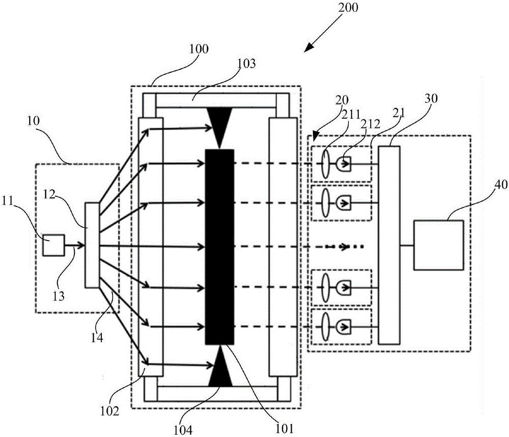
[0018] figure 1 It is a structural schematic diagram of the active laser type solid rocket propellant burning rate dynamic testing device of the present invention.

[0019] Such as figure 1 As shown, the active laser type solid rocket propellant burning rate dynamic test device 200 is used to dynamically test the burning rate of the medicine bar 101 in the combustion chamber 100 .

[0020] The combustion chamber 100 is an airtight container, the pressure in which can be adjusted, and is used for testing under specific experimental conditions. The combustion chamber 100 includes a combustion chamber main body 103 and two light-transmitting windows 102...


PUM


Abstract

The invention provides a dynamic testing device and a dynamic testing method for a burning speed of an initiative laser type solid rocket propellant. The dynamic testing device comprises a laser emitting part, a photovoltaic conversion part and a signal processing part, wherein the laser emitting part comprises a laser emitting unit and a laser slice light converting unit; the photovoltaic conversion part is used for receiving the transmission light of the laser slice light passing through the powder strip and converting a light signal of the transmission light into an electric signal; the signal processing part is used for processing the electric signal, acquiring the data corresponding to the electric signal and acquiring the burning speed of the powder strip on the basis of the data; the photovoltaic conversion part comprises a plurality of photovoltaic conversion units which are arranged longitudinally and in parallel with the powder strip; the photovoltaic conversion units are parallel to each other and are vertical to the powder strip. The burning speed of the propellant can be dynamically acquired by recording the condition of the change in mutational site of the transmission light signal along with the time after the powder strip is ignited. The dynamic testing device and dynamic testing method for the burning speed of the initiative laser type solid rocket propellant provided by the invention can overcome the defects of easiness in being influenced by pressure and low test precision of a photoelectric method and have the advantages of simple structure, non-contact mode and high test precision.

Description

technical field [0001] The invention belongs to the field of testing the burning rate of solid rocket propellant, in particular to an active laser type solid rocket propellant burning rate dynamic testing device and method. Background technique [0002] The burning rate parameter of solid rocket propellant is one of the important parameters to characterize the performance of the propellant. At present, the burning rate test is mainly carried out by making the solid propellant into a drug strip. The test methods include the target line method, the underwater acoustic emission method, and the photoelectric method. law etc. [0003] The photoelectric method for testing the burning rate of solid rocket propellant is to open an optical window parallel to the drug bar on the side wall of the tester, and arrange two photoelectric sensors at the upper and lower ends of the drug bar to receive the flame radiation signal generated by the propellant combustion, and record The burn tim...

Claims


Application Information

Patent Timeline
IPC IPC(8): G01N31/12G01P3/68
CPCG01N31/12G01P3/68
Inventor 杨斌武强郭浩然平力王占平于天泽
Owner UNIV OF SHANGHAI FOR SCI & TECH
Learn More