Method and apparatus for mass based dispensing

a technology of mass and apparatus, applied in the field of dispensers, can solve problems such as system more susceptible to changes

Active Publication Date: 2004-12-09
ECOLAB USA INC
View PDF40 Cites 109 Cited by
  • Summary
  • Abstract
  • Description
  • Claims
  • Application Information

AI Technical Summary

Benefits of technology

[0010] In another embodiment, the invention is a method of loading a container of concentrate to a dispenser. The dispenser has a housing having a cavity for receiving the container, a product holder is carried by a scale and a moveable container holder and a cover is operatively connected to the moveable container holder. The method includes raising the cover, wherein movement of the cover raises the container holder off of the product holder. Inserting the container into the moveable container holder and lowering the cover, wherein the container holder is lowered on to the product holder, whereby excessive shock to the scale is prevented during loading.

Problems solved by technology

While such systems are useful, the systems are more susceptible to changes depending upon the amount of product that is being exposed to the diluent, the pressure at which the diluent is supplied or the temperature at which the diluent is supplied.
Again, this system has its own unique problems such as the necessity of adding chemistry to the product to allow the dilute concentration to be tested.
Further, the conductivity based dispensers typically require on / off cycling to achieve an asymptotic approach to the concentration set point.

Method used


Image

  • Method and apparatus for mass based dispensing
  • Method and apparatus for mass based dispensing
  • Method and apparatus for mass based dispensing

Examples


Embodiment Construction

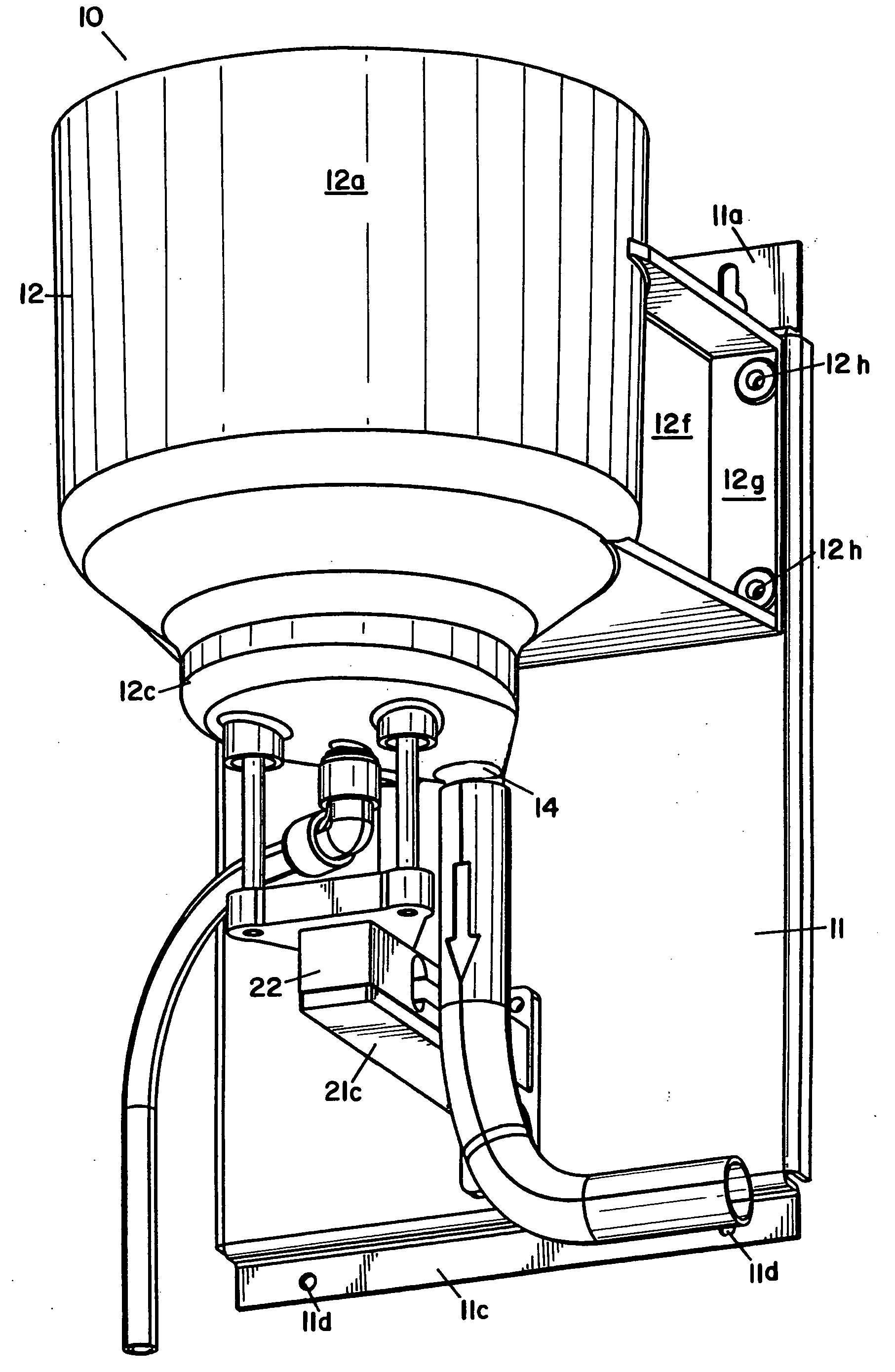
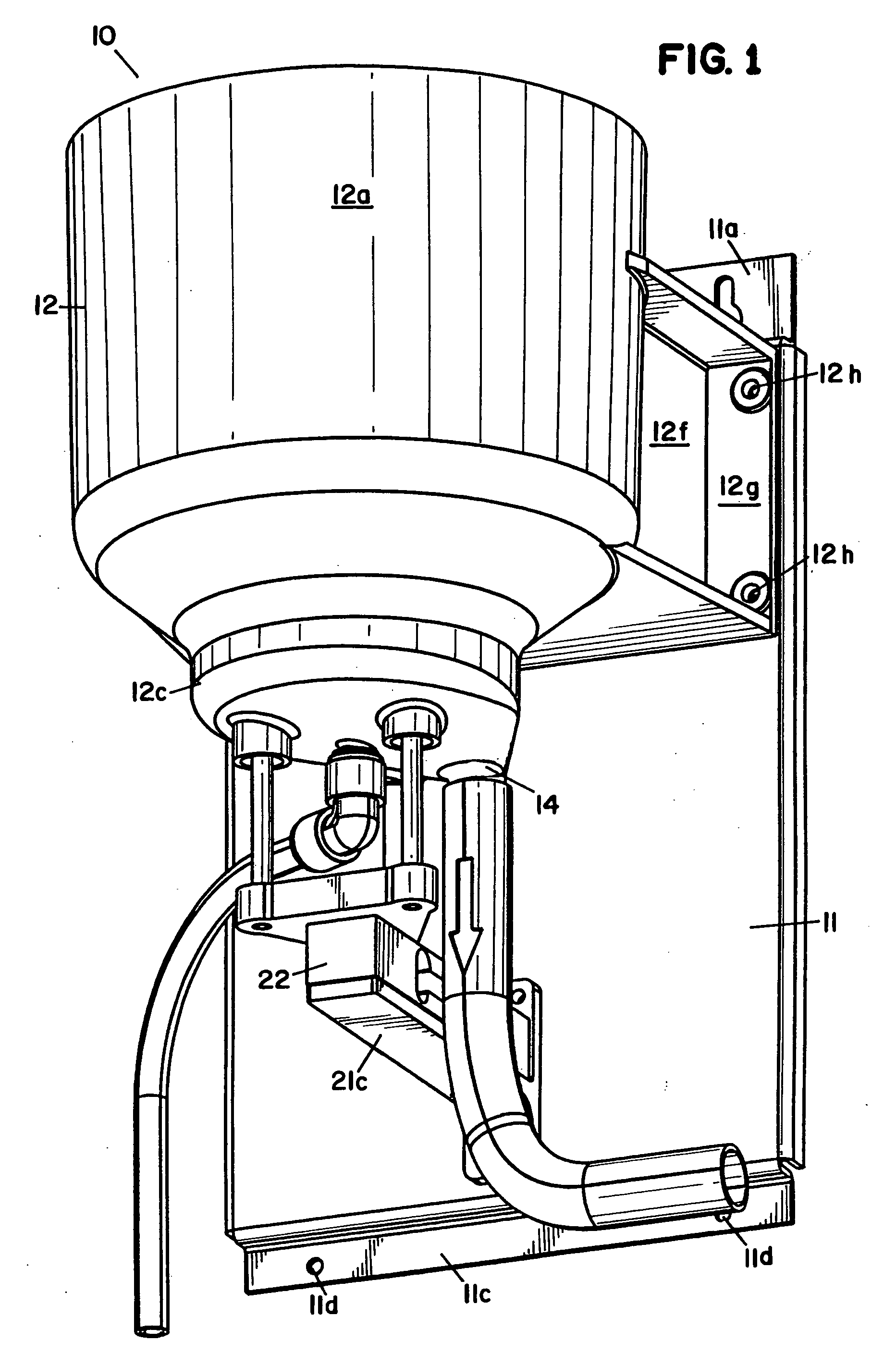
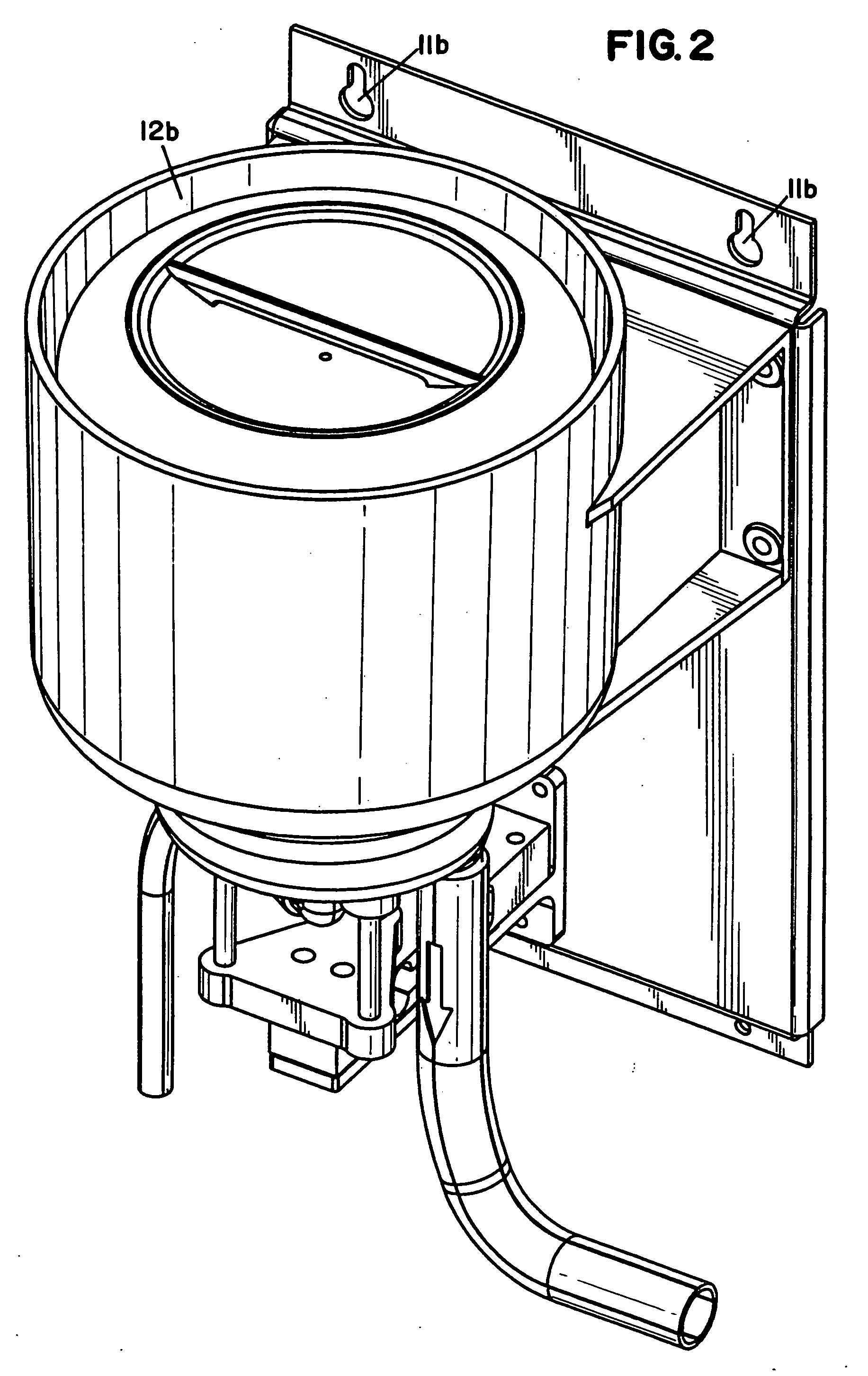
[0035] Referring to the drawing, wherein like numerals represent like parts throughout the several views, there is generally disclosed at 10 a dispenser. The dispenser 10 is shown mounted to a mounting panel 11 or other suitable mounting structure, which is suitable for mounting on a wall or other support surface (not shown). The support surface is typically a wall of a room, or a surface that is sturdy enough to support the dispenser 10. However, it is understood that the dispenser 10 may be mounted in various ways, well known in the art, including a free-standing dispenser. The mounting panel 11 is a support member and has a top flange 11a having two key way openings 11b. The openings 11b has a larger segment to allow the openings 11b to be placed over the head of a mounting bolt (not shown). The mounting bolt is secured into a mounting surface and the dispenser then drops down on the mounting bolt and is supported by the closed top of the openings 11b. A bottom flange 11c has two...


PUM

PropertyMeasurementUnit
weightaaaaaaaaaa
weightaaaaaaaaaa
weightaaaaaaaaaa

Abstract

A dispenser (200) dispenses an amount of concentrate in a container (204) using a diluent to form a use solution. A dispenser includes a housing (201). A product holder (210) is positioned to support the container (204) with the concentrate in the cavity of the housing. The product holder (210) carried by a scale (240), wherein weight of the concentrate is concerned. A moveable container holder (215) is moveable between a first position and a second position. The container holder is positioned between the housing (201) and the container (204). A cover (216) is operatively connected to the container holder (215) at a connection. A cam surface is adjacent the housing (201). The cover (216) has a cam (216d) for contacting the cam surface (201a), wherein when the cover (216) is moved from a closed position to an open position, the connection moves upward, thereby carrying the container holder (215) and the container (204) which are moved upward lifting the container (204) off of the product holder (210).

Description

[0001] This application is a Continuation-In-Part of U.S. patent application Ser. No. 10 / 437,257 filed May 12, 2003.[0002] 1. Field of the Invention[0003] This invention relates generally to dispensers and more particularly to a method and apparatus for dispensing a product based on mass.[0004] 2. Description of the Prior Art[0005] Dispensers that utilize a diluent to erode a product, such as a detergent, are well known. The product being dispensed is typically a solid product and can take the form of either a solid block of chemical, pellets or a cast product. One example of such a dispenser is found in U.S. Pat. No. 4,826,661 by Copeland et al. This patent discloses a solid block chemical dispenser for cleaning systems. The dispenser includes a spray nozzle for directing a uniform dissolving spray on to a surface of a solid block of cleaning composition. The nozzle sprays on the exposed surface of the solid block, dissolving a portion of the block and forming a product concentrate...

Claims


Application Information

Patent Timeline
Patent Type & Authority Applications(United States)
IPC IPC(8): A47L15/44B01F1/00B01F15/00B01F15/04C02F1/68D06F39/02
CPCB01F1/0027B01F15/00123B01F15/00194B01F15/00344B01F15/0445C02F1/688D06F39/02D06F39/026G01G13/024B01F21/22B01F35/2117B01F35/20B01F35/2211B01F35/881
Inventor MEHUS, RICHARD J.JOHNSON, ROYCE D.
Owner ECOLAB USA INC
Why Eureka
Try Eureka