
Sheet folding device, sheet processor having the same, and image forming system

Active Publication Date: 2004-12-16
RICOH KK
View PDF17 Cites 53 Cited by
  • Summary
  • Abstract
  • Description
  • Claims
  • Application Information

AI Technical Summary

Benefits of technology

[0010] More specifically, the object of the present invention is to provide a sheet folding device, sheet processor having the same, and image forming system which can process with space-saving, low cost and high productivity.
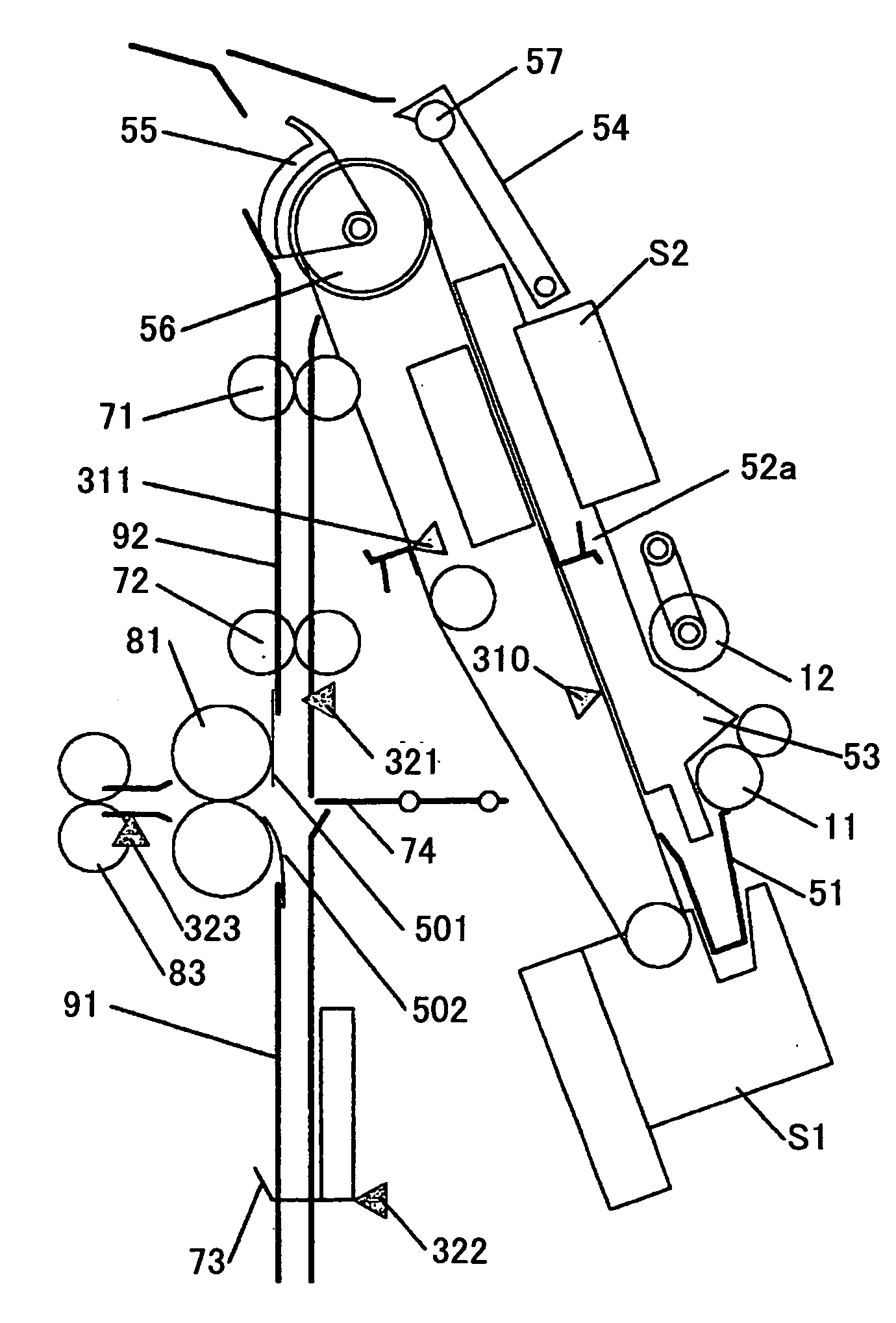
[0020] Free ends of the first guide member and the second guide member may be positioned so as to prevent pressure-welding by the folding rollers, which corresponds to a stiffness force of the sheet or the sheet stack, at the time when the sheet or the sheet stack is pushed into the nip of the folding rollers by the folding plate.

Problems solved by technology

At this time, when a head end of the sheet stack passes the side of the folding roller couple exposed to a conveying path, the sheet stack comes in contact with the folding roller so that the end of the sheet may become folded and a jammed paper condition may occur.
However, according to the above mentioned method, the distance between the nip position of the folding rollers and the folding plate, being out at a side of a direction facing the path, is long.
Because of this, the moving distance of the folding plate increases and therefore a space for arranging a driving part of the folding plate becomes large and a large space is required.
Furthermore, since the time for moving the folding plate increases, not only does the device size become large but also productivity of the machine becomes low.
However, in the above mentioned related art, although a small space may be required, the mechanism for moving out is required and so that the cost increases.

Method used


Image

  • Sheet folding device, sheet processor having the same, and image forming system
  • Sheet folding device, sheet processor having the same, and image forming system
  • Sheet folding device, sheet processor having the same, and image forming system

Examples


Embodiment Construction

[0057] A description is next given, with reference to FIG. 1 through FIG. 16, of embodiments of the present invention.

[0058] 1. Mechanical Structure

[0059] 1.1 Whole Structure

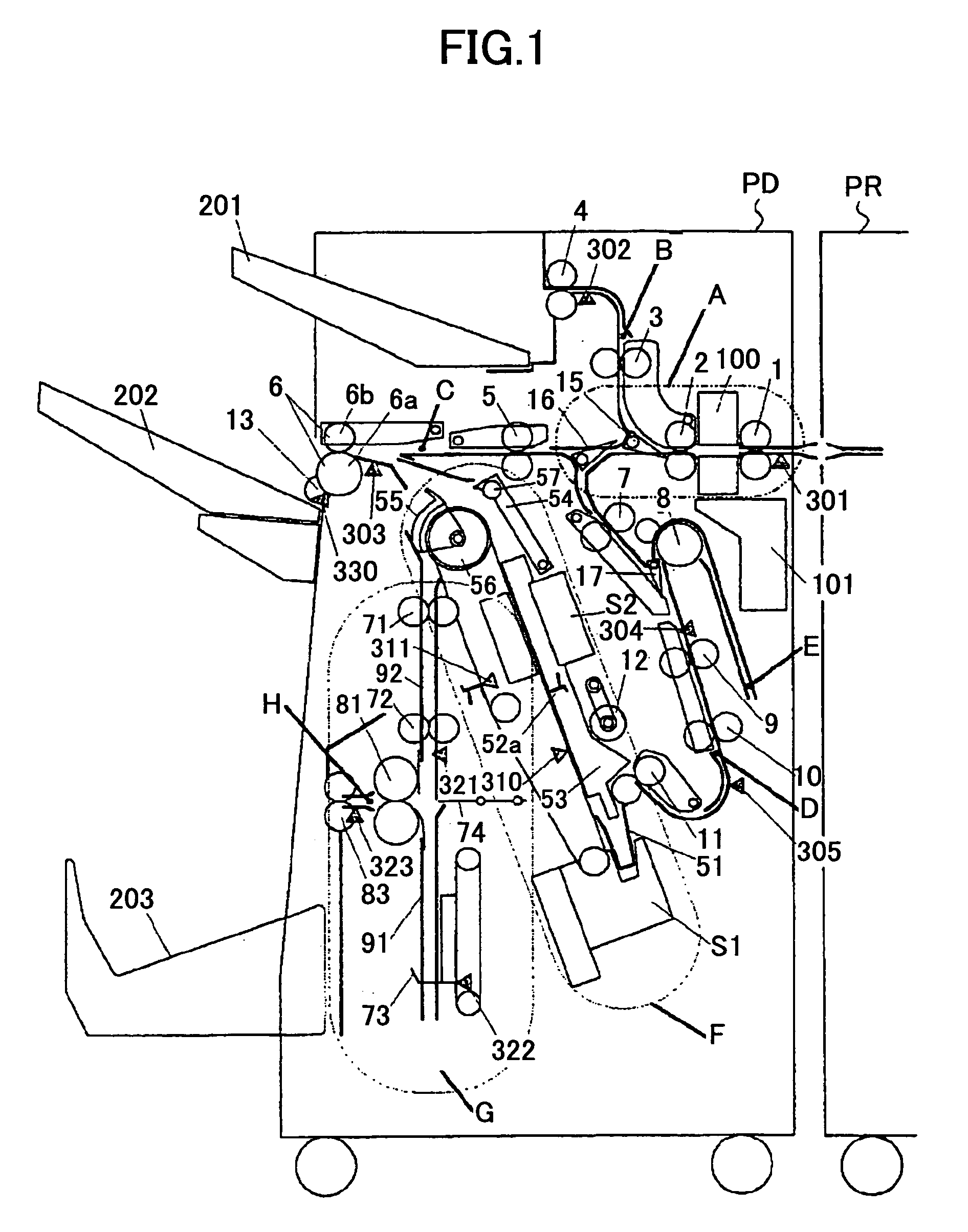
[0060] FIG. 1 shows a system structure of an image forming system, formed by a post-treatment device PD as a sheet processor of an embodiment of the present invention and an image forming device PR. More specifically, FIG. 1 shows the whole of the sheet post-treatment device and a part of the image forming device.

[0061] Referring to FIG. 1, the post-treatment device PD is operatively connected to one side of the image forming device PR. A sheet or recording medium driven out of the image forming device PR is introduced into the post-treatment device PD. The sheet is then conveyed through a path A where post-processing means for post-processing a single sheet is located. In the illustrative embodiment, the post-processing means on the path A is implemented as a punch unit or punching means 100. Subsequently, the ...


PUM

PropertyMeasurementUnit
Forceaaaaaaaaaa
Surface smoothnessaaaaaaaaaa
Elasticityaaaaaaaaaa

Abstract

A sheet folding device includes a folding plate configured to push out a sheet or sheet stack in a direction pre-set against a conveying path; a couple of folding rollers configured to push the sheet being pushed into a nip of the folding roller couple; and a guide part configured to guide the sheet or the sheet stack so as to prevent the sheet from coming contact in with the folding rollers in the conveying path where the sheet or the sheet stack is conveyed. The sheet or the sheet stack is folded while being put between and conveyed by the couple of the folding rollers.

Description

[0001] 1. Field of the Invention[0002] The present invention generally relates to (1) sheet folding devices whereby a sheet stack is accumulated, arranged, and folded; (2) sheet processors which are provided to image forming devices, such as copiers, printers, or printing machines, in a body or separately, and whereby predetermined processes such as classification processes, stacking processes, binding processes, and center-binding bookbinding processes are performed on the sheets (recording media) where the images are formed so that the sheets are discharged; and (3) image forming systems having the sheet processors and the image forming devices.[0003] 2. Description of the Related Art[0004] There is extensively used a post-treatment device arranged at the downstream side of an image outputting device, such as a copier or printer, for, e.g., binding sheets driven out of the image forming apparatus. Today, even a post-treatment device with multiple advanced functions including an ed...

Claims


Application Information

Patent Timeline
IPC IPC(8): B65H29/52B65H45/18G03G15/00
CPCB65H29/52B65H45/18B65H2405/22G03G15/6538G03G2215/00877
Inventor SUZUKI, NOBUYOSHITAMURA, MASAHIRO
Owner RICOH KK
Learn More