Program for voice talking, voice talking method, and voice talking apparatus

a voice and voice technology, applied in the field of voice talking methods, can solve problems such as the effect of loading on a permanent network associated with call control

Inactive Publication Date: 2004-12-23
KK TOSHIBA
View PDF5 Cites 41 Cited by
  • Summary
  • Abstract
  • Description
  • Claims
  • Application Information

AI Technical Summary

Problems solved by technology

However, in the mobile IP, since the address management server manages the table of the home address and the destination address to be moved in batch, the table is not managed at the term

Method used


Image

  • Program for voice talking, voice talking method, and voice talking apparatus
  • Program for voice talking, voice talking method, and voice talking apparatus
  • Program for voice talking, voice talking method, and voice talking apparatus

Examples


first embodiment

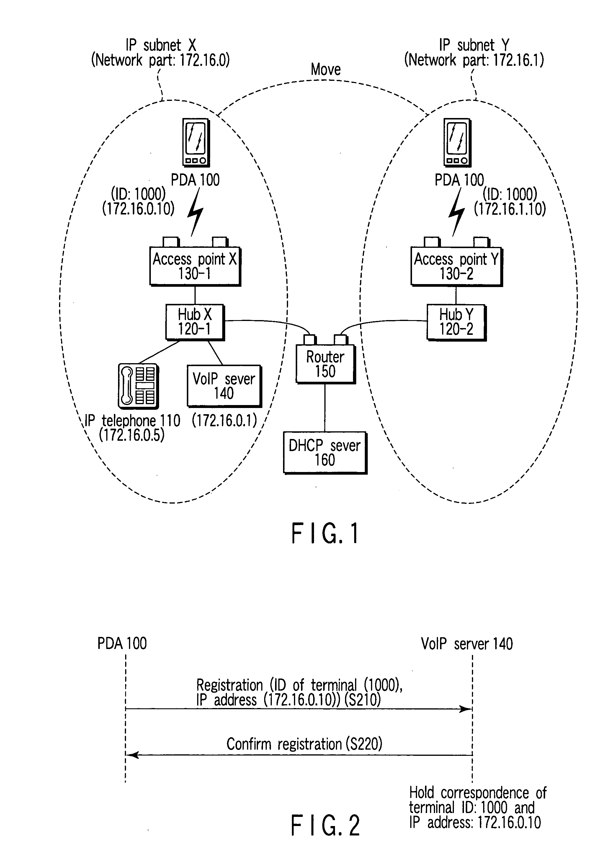
[0039] In the present invention, both a call control packet and a voice packet are transmitted and received via a VoIP server 140.

[0040] (Talking Method Without Movement)

[0041] A talk between a PDA (Personal Digital Assistant) 100 which is a VoIP terminal and an IP telephone 110 will be described here.

[0042] FIG. 4 is a diagram showing a sequence in the case where the IP telephone 110 makes a call to the PDA 100. The IP telephone 110 specifies the PDA's ID (1000) as a destination, and requests call establishment to the VoIP server 140 (S310). The VoIP server 140 relays the call establishment request to the PDA 1000 by referring to a correlation table of an ID and an IP address (S320). A response signal from the PDA 100 also relays the VoIP server 140, and is transmitted to the IP telephone 110 which is a call departure source (S330, S340). Here, H.323 is used as a series of call control protocols.

[0043] Then, voice talking is started between the IP telephone 110 and the PDA 100, and...

second embodiment

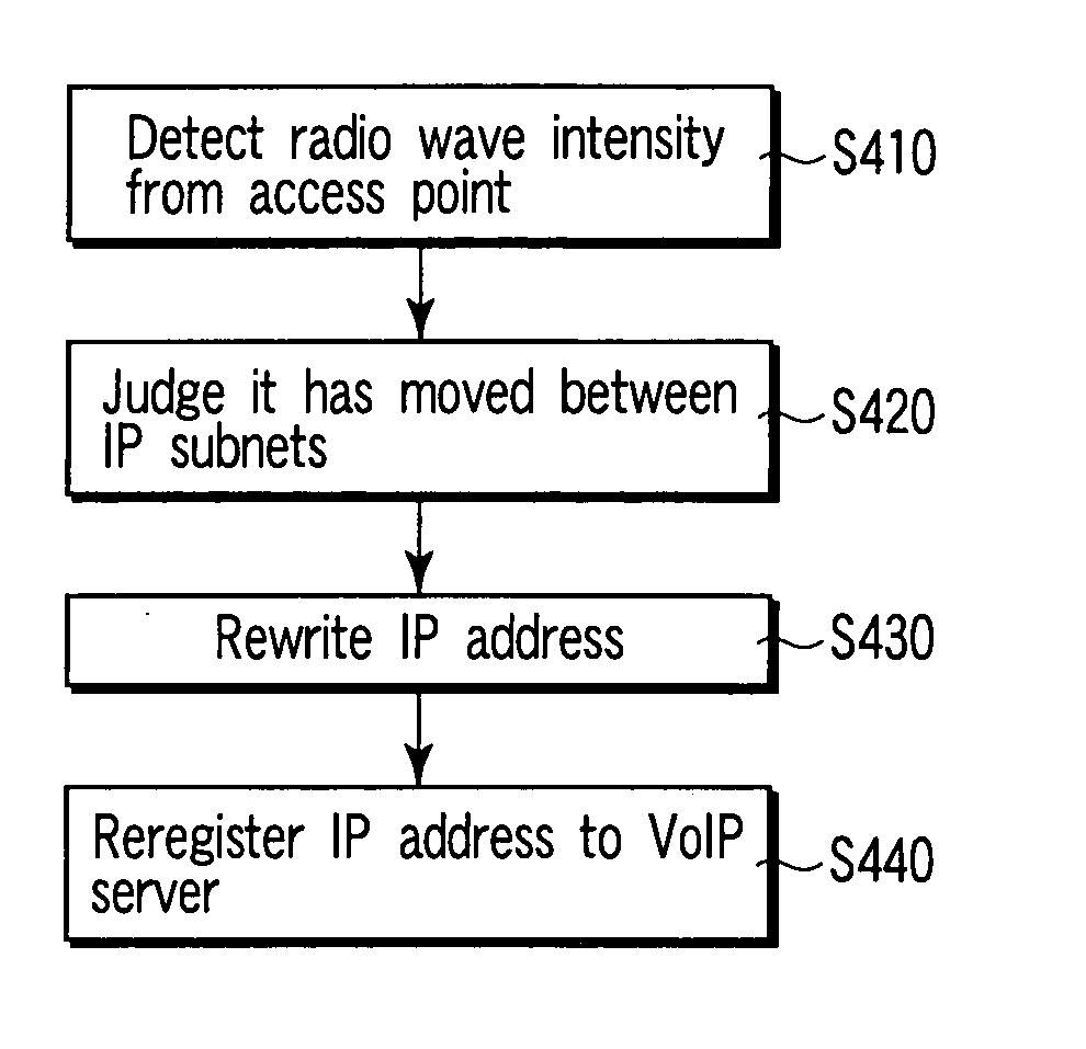
[0052] FIG. 7 shows a call control sequence according to a second embodiment of the present invention. In the present embodiment, a call control packet is exchanged via a VoIP server 140, and a voice packet is directly transmitted and received at an end to an end. The VoIP server 140 has means for transmitting a call control signal setting a required state to a terminal, thereby the terminal changing a called remote IP address or the like during talking at an end to an end. In this manner, even in the case where a talking terminal has changed a subnet (S610), the VoIP server can notify a talking party of the IP address change of the moved terminal, and thus, can achieve talking continuation (S620 to S650).

third embodiment

[0053] FIG. 8 shows a call control sequence according to a third embodiment of the present invention. In the present embodiment as well, a call control packet is exchanged via a VoIP server 140, and a voice packet is transmitted and received at an end to an end. In the case where the VoIP server 140 is not provided with means according to the second embodiment, and a terminal whose subnet has been changed (S710) has a talk call, this terminal itself notifies a talking party of a request for changing a destination IP address of the voice packet (S720 to S750).

[0054] The above-described embodiments are provided as preferred specific examples of the present invention, and thus, a variety of technically preferable limitations are applied. However, of course, these limitations can be combined and changed properly within departing from the spirit of the invention.

[0055] For example, since the IP telephone 110 knows the ID of the PDA 100, but does not know an IP address, the IP telephone i...


PUM


Abstract

A computer program, which is used to voice talking to cause an information terminal to execute voice talking, managing an ID of the information terminal and a first address over a first network, stores instructions for execution on a computer system enabling the computer system to perform determining that the information terminal moves over a second network which is different from the first network, acquiring a second address over the second network, and transmitting a request for re-registering a combination of the second address and the ID instead of the first address into another device having a combination of the first address and the ID registered therein.

Description

[0001] This application is based upon and claims the benefit of priority from prior Japanese Patent Application No. 2003-094364, filed Mar. 31, 2003, the entire contents of which are incorporated herein by reference.[0002] 1. Field of the Invention[0003] The present invention relates to a voice talking method using VoIP (Voice over Internet Protocol, Internet telephone), and more particularly, to a VoIP terminal mobile management method.[0004] 2. Description of the Related Art[0005] With the spread of Internet, a data transfer speed over an IP network is improved. Thus, in an Internet telephone as well, talking between inside networks (hereinafter, referred to as "subnets") such as LAN (Local Area Network) as well as talking between different types of subnets can be carried out.[0006] Therefore, a VoIP terminal which is a portable information device enabling voice talking may move between subnets. In this case, the VoIP terminal disables voice talking by using an IP address before m...

Claims


Application Information

Patent Timeline
IPC IPC(8): H04L12/66H04L45/24H04L45/80H04W36/36H04M11/00H04W60/04H04W80/04H04W80/10
CPCH04L29/06027H04L29/12301H04L29/12311H04L61/2076H04L61/2084H04W60/04H04W80/04H04L65/1083H04L61/5076H04L61/5084H04L65/1101
Inventor KASHIMOTO, SHINICHIARAKI, MOTOHISA
Owner KK TOSHIBA
Why Eureka
Try Eureka