Fluid filled vibration damping device

Inactive Publication Date: 2004-12-30
SUMITOMO RIKO CO LTD
View PDF7 Cites 31 Cited by
  • Summary
  • Abstract
  • Description
  • Claims
  • Application Information

AI Technical Summary

Benefits of technology

0020] A second mode of the invention is a fluid-filled vibration damping device according to the first mode, wherein the second mounting member is fixed to the rubber elastic body, and the first mounting member is formed independently of the rubber elastic body, while the rebound stop mechanism includes a rebound stop rubber being fixed to the first mounting member. In the fluid-filled vibration damping device of construction according to this mode, since the first mounting member is formed independently of the rubber elastic body, and a rebound stop rubber constituting the rebound stop mechan

Problems solved by technology

Extensive researches conducted by the inventors has revealed that the fluid filled vibration damping devices of conventional design may possibly suffer from deterioration in the damping performance, when a relatively large load is input to the rubber elastic body in the opposite direction (rebound direction) from the direction in which initial load is exerted (bound direction) due to the distributed support load of a power unit, that is, in the direction that expands the volume of the fluid chamber.
Therefore, when a relatively large load is input in the opposite direction from the direction in which initial load is exerted on the rubber elastic body, the sealed fluid undesirably exerts constraining force on the rubber elastic body in a direction tending to inhibit elastic deformation of the elastic body.
This creates a rubber elastic body dynamic spring constant that is greater than that of a rubber elastic body alone, result

Method used


Image

  • Fluid filled vibration damping device
  • Fluid filled vibration damping device
  • Fluid filled vibration damping device

Examples


first embodiment

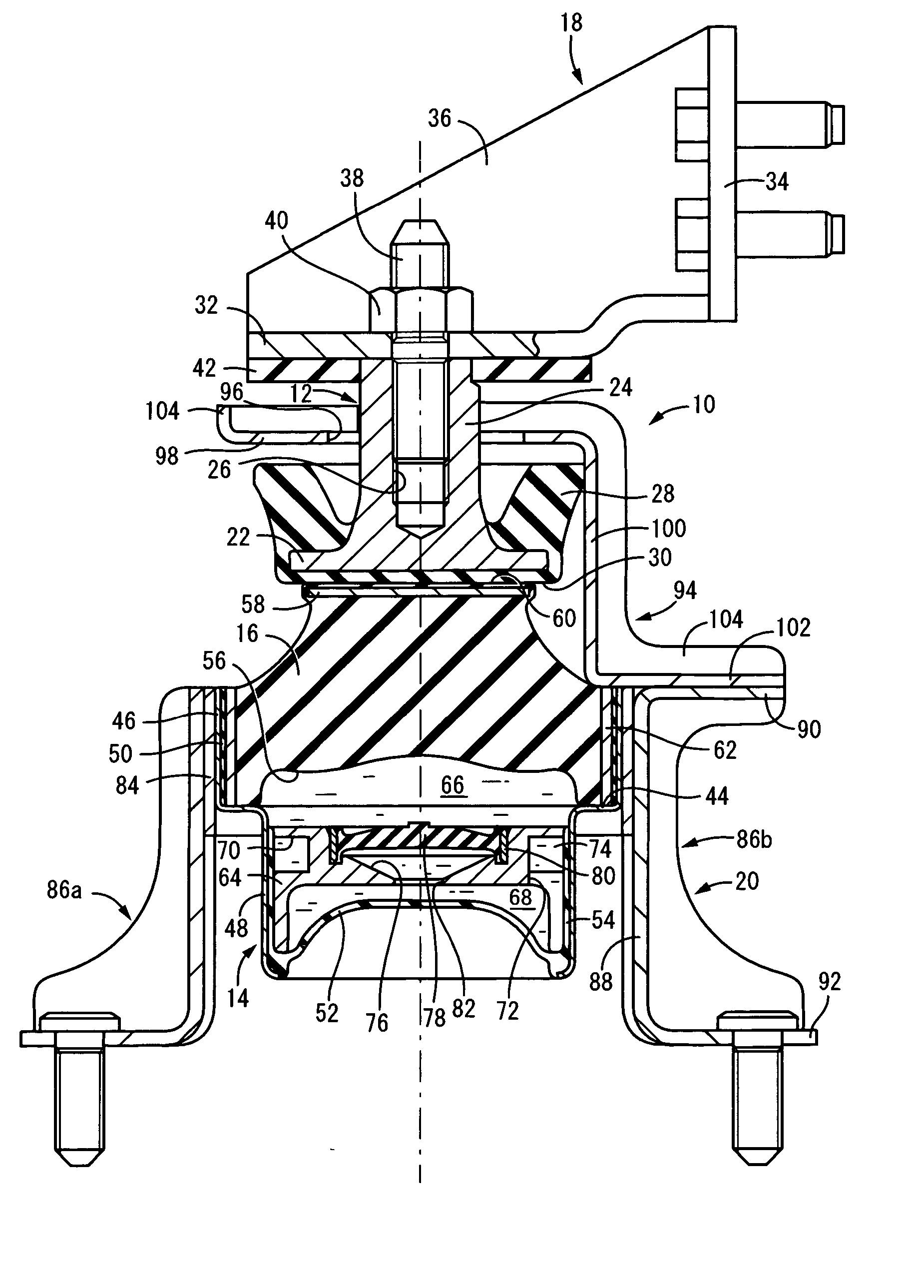
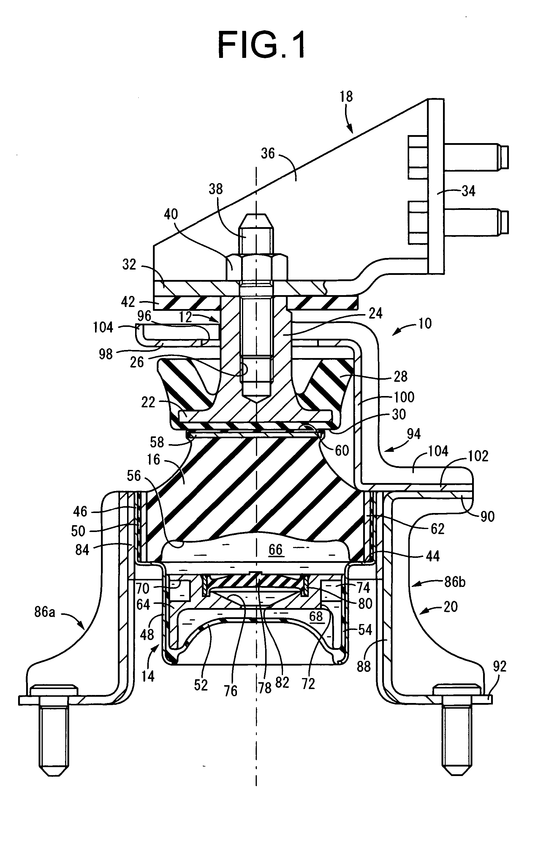
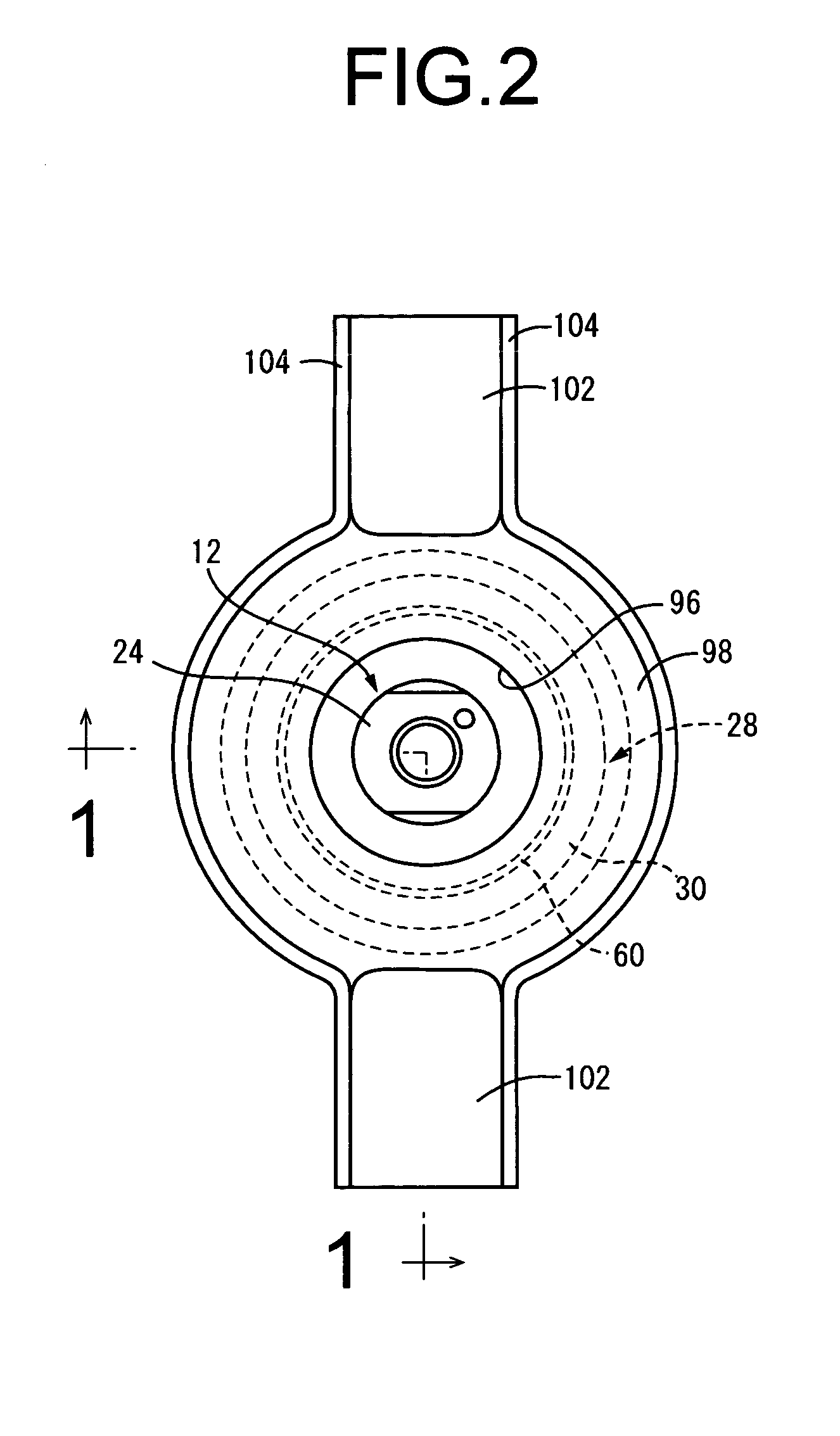
[0031] Referring first to FIG. 1, there is shown a fluid-filled vibration-damping device in the form of an engine mount 10 for automotive vehicles, which is constructed according to the invention. The engine mount 10 has a structure comprising a rubber elastic body 16 disposed between a metallic first mounting member 12 fixable to a power unit (not shown), and a metallic second mounting member 14 fixable to a body of the vehicle (not shown). The first mounting member 12 is fixed via a power unit-side bracket 18 to the power unit, while the second mounting member 14 is fixed via a body-side bracket 20 to the body, so that the power unit is mounted on the body in vibration-damping fashion. With the engine mount 10 of this embodiment installed in this state, the engine mount 10 bears a distributed support load of the power unit or static load exerted thereon in the generally vertical direction in FIG. 1, and exhibits effective damping action against vibration applied thereto in the gen...

third embodiment

[0068] FIGS. 5 and 6 illustrates a fluid-filled vibration-damping device in the form of an automotive engine mount 120 of construction according to the invention. This engine mount 120 has a construction in which a rubber elastic body 126 is disposed between a metallic first mounting member 122 fixable to the power unit, and a metallic second mounting member 124 fixable to the body. The first mounting member 122 is fixed to the power unit, while the second mounting member 124 is fixed to the body, so that the power unit is superimposed on the body in a vibration-damping manner. With the engine mount 120 of this embodiment installed as stated above, power unit distributed support load is input in the generally vertical direction in FIGS. 5 and 6, and the engine mount 120 exhibits excellent vibration damping effect with respect to input vibration in the generally vertical direction in FIGS. 5 and 6.

[0069] Described in detail, the first mounting member 122 has an overall long plate con...

fourth embodiment

[0094] Namely, FIGS. 7 and 8 shows an engine mount 202 of construction according to the invention. This engine mount 202 comprises: a metallic inner sleeve 204 constituting a first mounting member; a metallic outer sleeve 206 constituting a second mounting member; and a rubber elastic body 208 interposed between the inner and outer sleeves 204, 206. The inner sleeve 204 is attached to the body side, while the outer sleeve 206 is attached to the power unit side. In FIGS. 7 and 8, the inner sleeve 204 and outer sleeve 206 are shown positioned generally concentrically, with the distributed support load of the power unit acting in the vertical direction in the drawing.

[0095] Described more specifically, the inner sleeve 204 has a thick-walled, small-diameter cylindrical shape, to the outer circumferential surface of which is bonded a cushion rubber 210 as a rebound stop rubber projecting outward in the axis-perpendicular direction, through vulcanization of a rubber material for forming ...


PUM


Abstract

A fluid filled vibration-damping device includes an elastic body disposed between a first mounting member and a second mounting member and partially defines a fluid chamber having a non-compressible fluid sealed therein, and exhibits vibration damping action on the basis of flow action of the non-compressible fluid created within the fluid chamber during vibration input. At least one mounting member from among the first and second mounting members is formed independently of the elastic body and is disposed in abutment with the elastic body in an initial load acting direction, while making the mounting member displaceable away from the rubber elastic body in a opposite direction from the initial load acting direction. A rebound stop mechanism for limiting displacement of the mounting member away from the rubber elastic body in a cushion-wise fashion is disposed between the first and second mounting members.

Description

INCORPORATED BY REFERENCE[0001] The disclosure of Japanese Patent Application No. 2003-188520 filed on Jun. 30, 2003 including the specification, drawings and abstract is incorporated herein by reference in its entirety.BACKGROUND OF THE INVENTION[0002] 1. Field of the Invention[0003] The present invention pertains to a fluid filled vibration damping device that exhibits vibration damping effect on the basis of flow action of a non-compressible fluid sealed therein, and in particular relates to a fluid filled vibration damping device suitable for use in an automotive engine mount, body mount, or cab mount, for example.[0004] 2. Description of the Related Art[0005] There have been widely used in a variety of fields vibration damping devices each having a rubber elastic body disposed between first and second mounting members fixable to components connected together in vibration isolating fashion. As one type of such vibration damping devices, there is known a fluid filled vibration da...

Claims


Application Information

Patent Timeline
IPC IPC(8): B60K5/12B62D27/04F16F13/08F16F13/10
CPCF16F13/101
Inventor MAENO, HAJIMEMURAMATSU, ATSUSHI
Owner SUMITOMO RIKO CO LTD
Why Eureka
Try Eureka