Stamping machine for mounting retention frame of heat sink to motherboard

a technology of heat sink and retention frame, which is applied in the direction of conduction heat transfer, connection contact member material, manufacturing tools, etc., can solve the problems of reducing heat transfer efficiency, cpu may overheat until it malfunctions or even damages beyond repair, and achieves convenient and safe mounting of retention frame.

Inactive Publication Date: 2005-01-06
HON HAI PRECISION IND CO LTD +1
View PDF9 Cites 14 Cited by
  • Summary
  • Abstract
  • Description
  • Claims
  • Application Information

AI Technical Summary

Benefits of technology

[0014] Accordingly, an object of the present invention is to provide a stamping machin

Problems solved by technology

If the distance is not uniform, this is known as “floating high.” When floating high exists, it results in non-uniform contact between the heat sink and the CPU, and reduced heat transfer efficiency.
The CPU may overheat until it malfunctions or is even damaged beyond repair.
However, the stamping machine 1 is liable to cause floating high, as detailed below.
Because bakelite has weak rigidity, it is easily deformed during the stamping process.
This increases costs.
Therefore the retention frame is not uniformly pressed onto the motherboard.
From the aspect of air pressure adjustment: The air pressure in the stamping machine 1 cannot be adjusted, therefore the operator cannot ensure that correct pressure is driving the pistons 7.
Such manual operati

Method used


Image

  • Stamping machine for mounting retention frame of heat sink to motherboard
  • Stamping machine for mounting retention frame of heat sink to motherboard
  • Stamping machine for mounting retention frame of heat sink to motherboard

Examples


Embodiment Construction

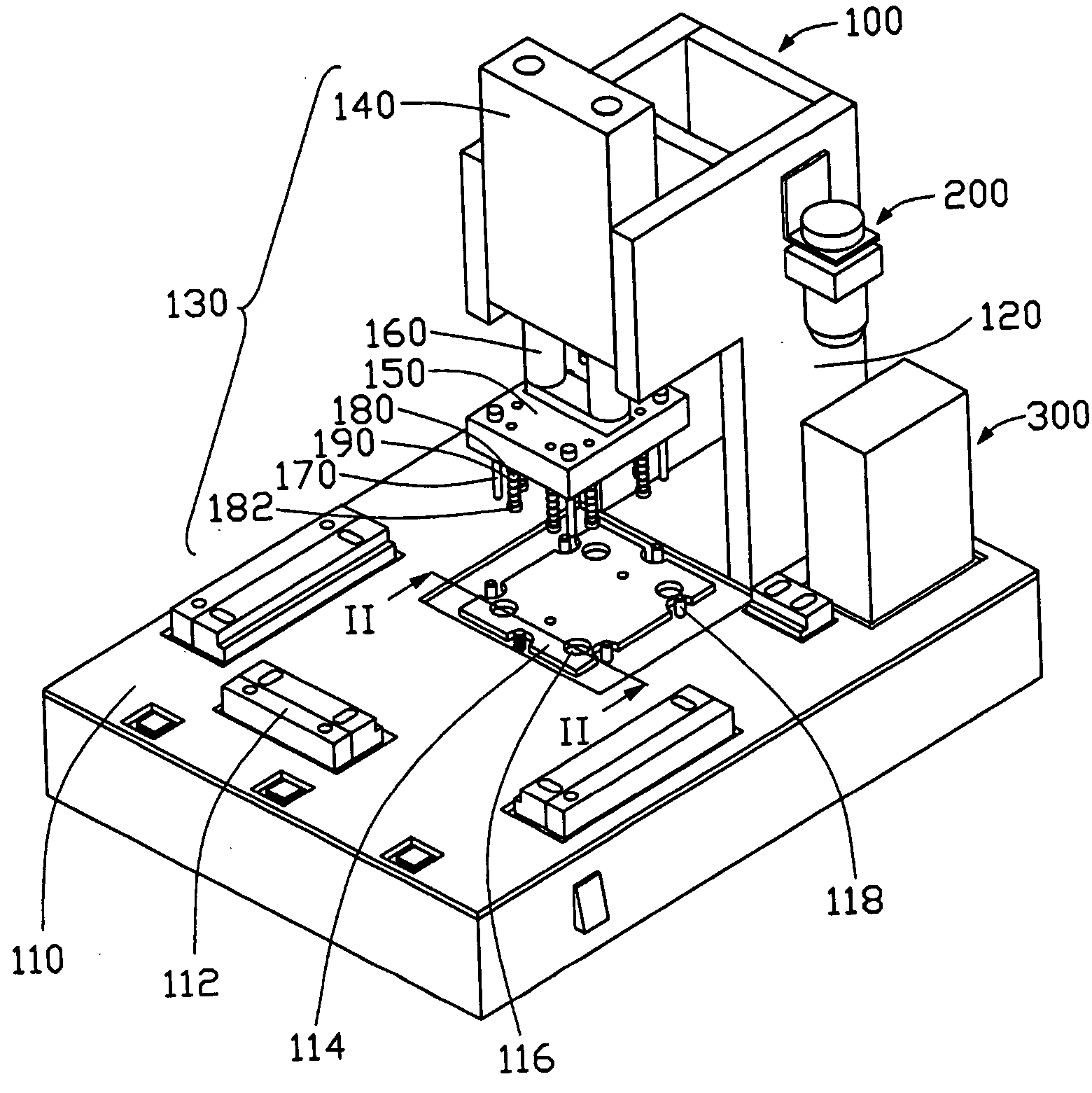
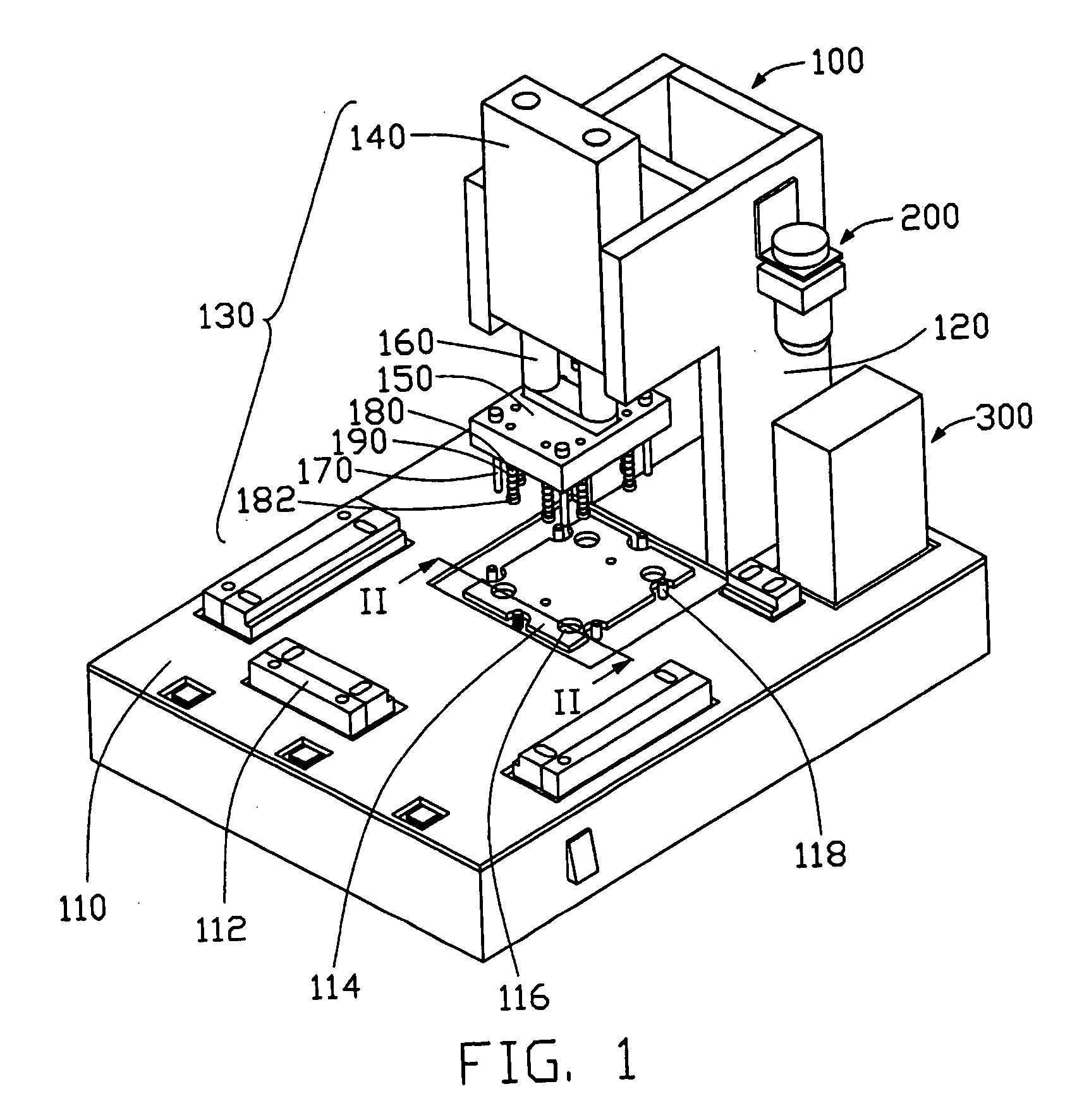
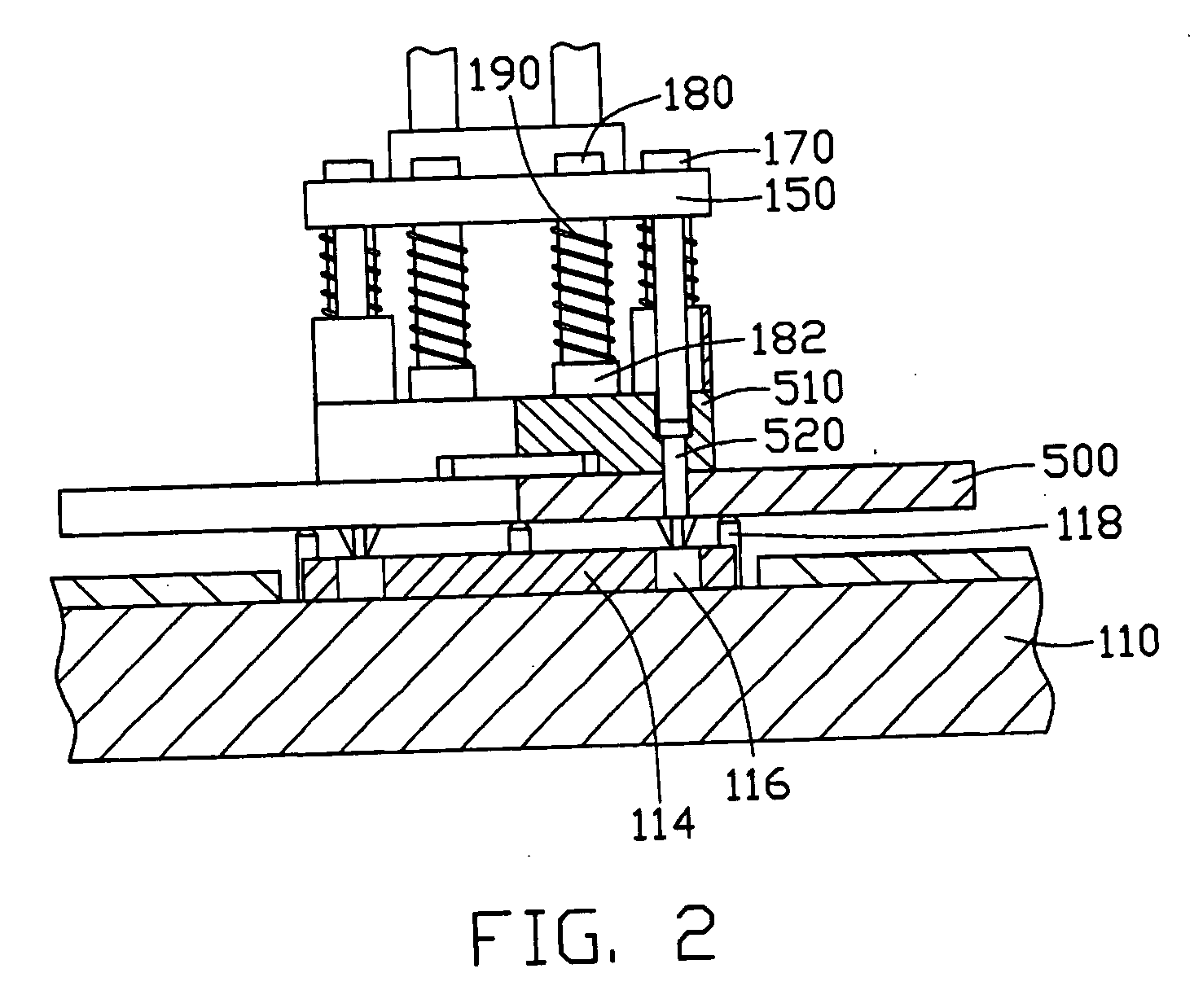
[0027] Referring to FIGS. 1 and 2, a stamping machine in accordance with the preferred embodiment of the present invention is for mounting a retention frame 510 of a heat sink (not shown) to a motherboard 500. The stamping machine comprises a machine body 100, an adjusting device 200, and a control unit 300.

[0028] The machine body 100 is made from metal or a metallic alloy such as aluminum alloy, for providing rigidity. The machine body 100 comprises a support plane 110 and a stamping arm 120. A plurality of adjustable positioning blocks 112 is provided on the support plane 110, for positioning of the motherboard 500 on the support plane 110. A stamping assembly 130 positioned at a forepart of the stamping arm 120 comprises a cylinder 140, a stamping block 150, and a base portion 114. The stamping block 150 is connected to bottom ends of a pair of pistons 160 of the cylinder 140. The base portion 114 is received in a recess of the support plane 110, directly beneath the stamping bl...


PUM

PropertyMeasurementUnit
Pressureaaaaaaaaaa

Abstract

A stamping machine for mounting a retention frame of heat sink (510) to a motherboard (500) includes a machine body (100), an adjusting device (200), and a controlling unit (300). The machine body comprises a support plane (110) and a stamping arm (120) extending upwardly from the support plane. A plurality of adjusting positioning blocks (112) is provided on the support plane for fittingly positioning the motherboard. A stamping assembly (130) is positioned at a forepart of the stamping arm comprises a cylinder (140), a stamping block (150) moveably connected to the cylinder, and a base portion (114) attached on the support plane corresponding to the stamping block. A plurality of stamping posts (170) extends from the stamping block and a plurality of retractable pressing pins (180) depends from the stamping block. A resilient member (190) is disposed around each of the pressing pins.

Description

BACKGROUND OF THE INVENTION [0001] 1. Field of the Invention [0002] The present invention relates to a stamping machine, and particularly to a stamping machine used for mounting a retention frame of a heat sink to a motherboard. [0003] 2. Description of the Prior Art [0004] Nowadays when a large heat sink is to be attached to a heat generating package such as a Central Processing Unit (CPU), a retention frame is often attached to a motherboard around the CPU in order to provide support for retaining the heat sink. There should be a suitable uniform distance between a bottom face of the retention frame and a top face of the motherboard. If the distance is not uniform, this is known as “floating high.” When floating high exists, it results in non-uniform contact between the heat sink and the CPU, and reduced heat transfer efficiency. The CPU may overheat until it malfunctions or is even damaged beyond repair. [0005] A conventional stamping machine for mounting a retention frame of a h...

Claims


Application Information

Patent Timeline
IPC IPC(8): H01R4/66H01R13/648H05K7/20H05K13/00
CPCH05K7/2039Y10T29/53065Y10T29/53174Y10T29/53039Y10T29/5327
Inventor FU, JUNLIN
Owner HON HAI PRECISION IND CO LTD
Why Eureka
Try Eureka