
Programming fixture for a virtual fencing system

a virtual fencing and fixture technology, applied in the field of fencing systems, can solve the problems of implicit relying on untested assumptions, loss of control of an animal, and animal in jeopardy

Inactive Publication Date: 2005-01-06
PETRAK
View PDF17 Cites 53 Cited by
  • Summary
  • Abstract
  • Description
  • Claims
  • Application Information

AI Technical Summary

Benefits of technology

The present invention is a wireless fencing system that avoids some of the costs and disadvantages of the prior art.
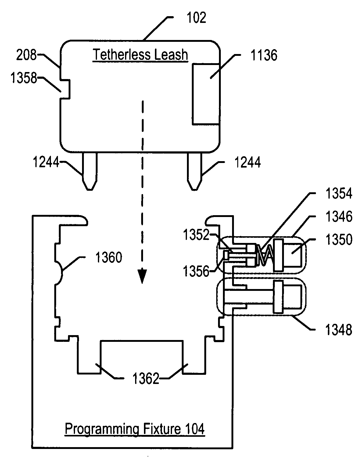
Furthermore, the programming fixture covers stimulus electrodes (used to deliver a “correction” to a monitored animal) during programming operations so that a user cannot be inadvertently shocked.

Problems solved by technology

Once breach occurs in a buried-wire system, the ability to control an animal is lost.
There are, however, some drawbacks to wireless fencing systems, such as the system described in the '546 patent.
One drawback is that when an original perimeter is expanded in response to a breach, a “free” zone in which the animal is permitted to roam is established between the original perimeter and the expanded one.
This might place an animal in jeopardy by allowing it to reach dangerous areas that it could not otherwise access from the original confinement zone.
A second drawback of some wireless fencing systems is that they implicitly rely on untested assumptions about the animal's return path.
But that path might not be safe and it might not be the shortest route back to the original containment zone.
A third drawback of some wireless fencing systems is that the programming interface (e.g., a button, etc.) is located on the control unit that is attached to the animal's collar.
To the extent that an animal that is wearing a control unit is exposed to rain, mud or free-standing water, as might occur when the animal is outside in inclement weather, the internals of the control unit can malfunction, thereby shortening the life of the control unit.
Furthermore, the programming interface might be inadvertently activated as the animal (e.g., dog, etc.) rolls over, plays, and the like.

Method used


Image

  • Programming fixture for a virtual fencing system
  • Programming fixture for a virtual fencing system
  • Programming fixture for a virtual fencing system

Examples


Embodiment Construction

The illustrative embodiment of the present invention is a wireless fencing system. A common use for the wireless fencing system described herein is to confine an animal within a region and / or exclude an animal from a region. As used hereinafter, the term “confine” means “confine and / or exclude” unless otherwise indicated.

For the purposes of this specification, the term “confinement zone” refers to the region in which the animal is confined (e.g., a pet owner's backyard, etc.) and the term “exclusion zone” refers to the region from which the animal is excluded (e.g., a garden, a pool, etc.). As used hereinafter, the term “confinement zone” means “confinement zone and / or exclusion zone” unless otherwise indicated. For the purposes of this specification, the term “animal” and its inflected forms mean pets, farm animals, livestock, and homo sapiens. Other terms are defined throughout this specification.

OVERVIEW

A brief overview of a wireless fencing system in accordance with the il...


PUM


Abstract

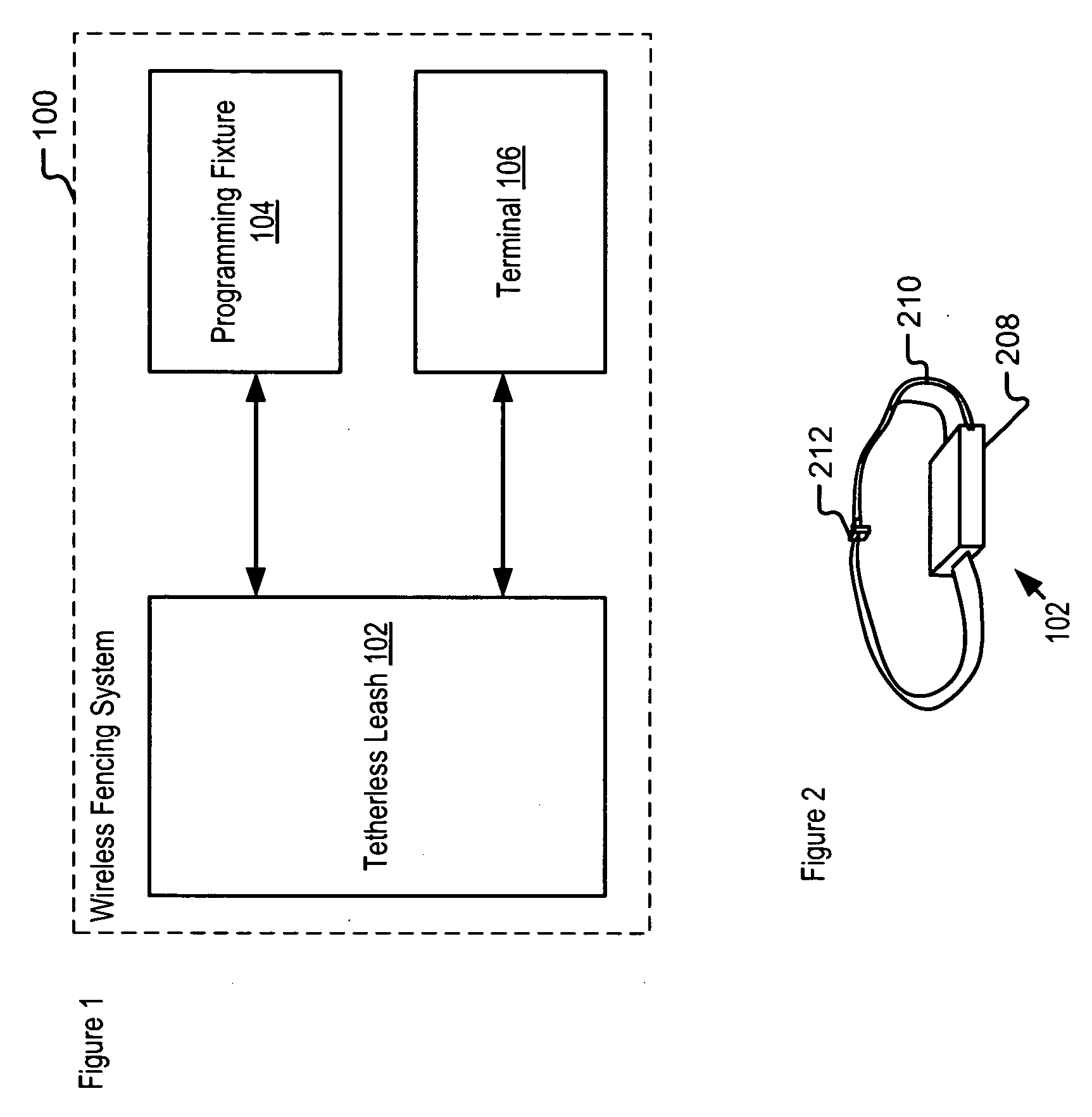
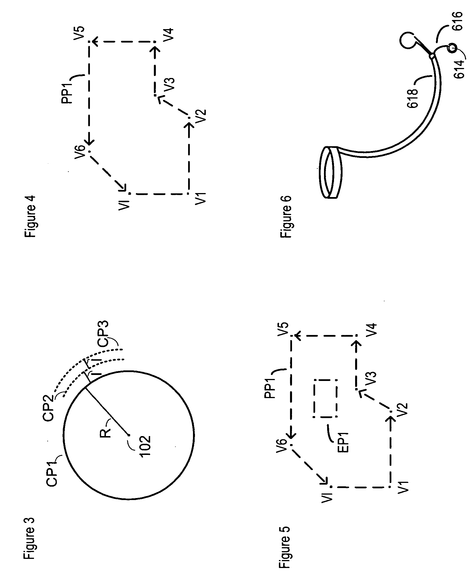
A wireless fencing system comprises a tetherless leash, a programming fixture, and, optionally, a terminal. The tetherless leash, which is attached to an animal that is to be monitored, establishes a “virtual” (i.e., barrier-free) perimeter based on geo-coordinates. The tetherless leash also monitors the position and movement of an animal relative to the perimeter, and delivers warnings, corrections, and praise to the animal in accordance with its programming. The programming fixture serves as a user interface during programming operations, since there are no exposed buttons by which a user can directly program the tetherless leash.

Description

FIELD OF THE INVENTION The present invention relates to fencing systems that do not use a physical boundary for containment or exclusion. BACKGROUND OF THE INVENTION Fencing systems that use a virtual barrier, rather than a physical barrier, to restrict the location and movement of animals are known in the art. There are two basic types of “virtual” fencing systems. One type of virtual fencing system employs a buried wire that defines a containment perimeter. The wire radiates a signal that can be sensed by a device worn by a monitored animal. As the monitored animal approaches the perimeter, the signal is sensed and the device delivers a correction (e.g., typically sound or an electric shock) to the animal to dissuade it from breaching the perimeter. The other type of virtual fencing system uses a wireless positioning system, such as GPS, to establish a perimeter and determine an animal's location. An example of such a “wireless” fencing system is disclosed in U.S. Pat. No. 6,5...

Claims


Application Information

Patent Timeline
IPC IPC(8): A01K15/02
CPCA01K15/023
Inventor GIUNTA, SALVATORE JOHNTHOMAS, WILLIAM EVAN JR.
Owner PETRAK
Learn More