Electronic filter assembly

a technology of electronic filter and assembly, applied in the direction of filter, transient suppressor details, coupling device connections, etc., can solve the problems of additional parts and expense, manual assembly steps, and require additional components

Inactive Publication Date: 2005-01-06
ARROW COMM LAB
View PDF44 Cites 15 Cited by
  • Summary
  • Abstract
  • Description
  • Claims
  • Application Information

AI Technical Summary

Benefits of technology

[0012] It is therefore an object of the present invention to provide an electronic filter construction that avoids the limits and problems associated with the prior art.

Problems solved by technology

Such an approach requires the additional parts and expense of o-rings and outer housing sleeves, and may require manual assembly of such parts.
However, such methods usually require additional components or manual assembly steps.

Method used


Image

  • Electronic filter assembly
  • Electronic filter assembly
  • Electronic filter assembly

Examples


Embodiment Construction

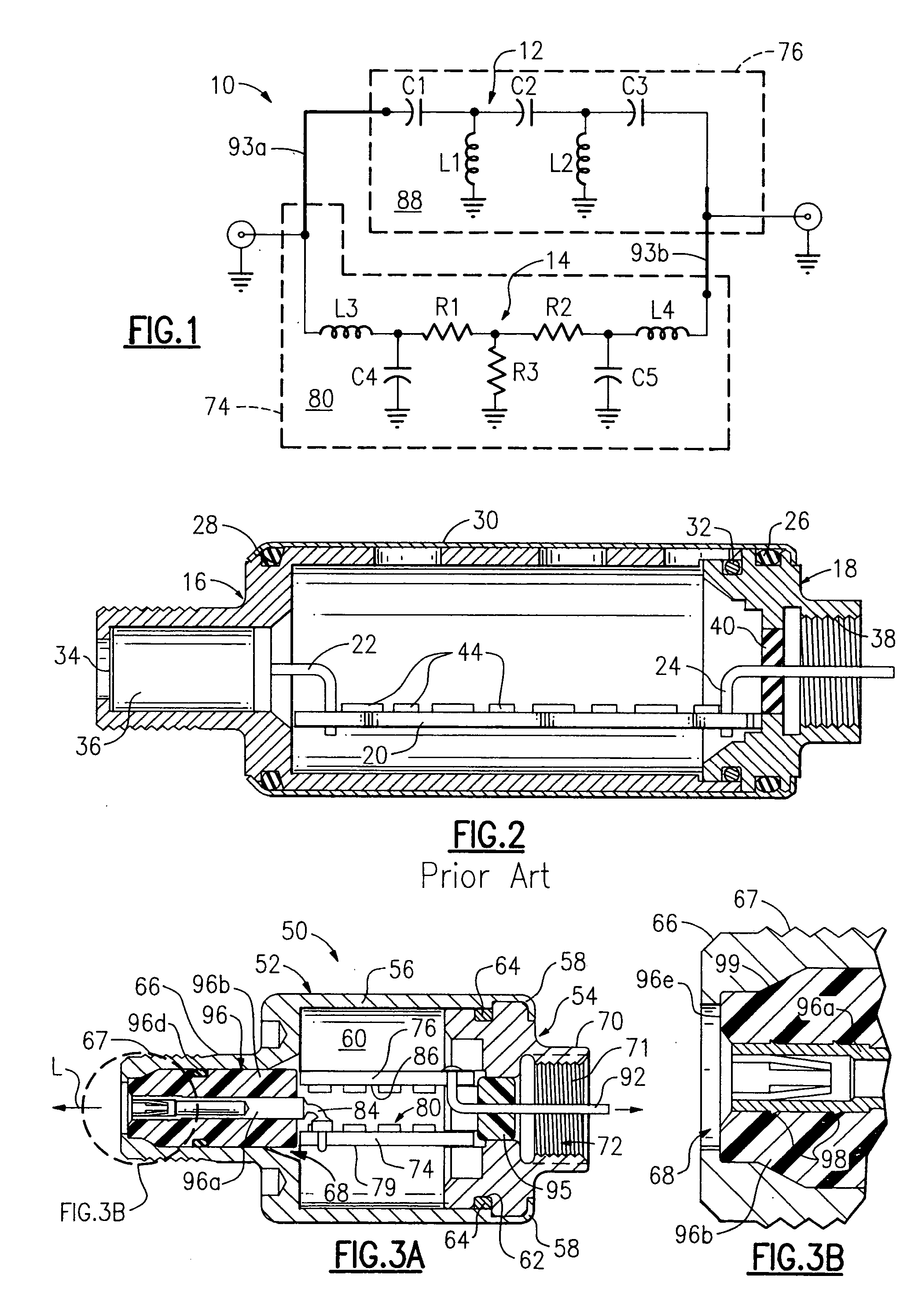
[0028] The filter assembly of the present invention is especially suited for dual (or parallel) path filter circuits. As understood in the art, dual path circuits include at least two separate circuit paths. Examples of dual path filters are diplex, windowed highpass, and some step attenuator filters. Referring now to FIG. 1, there is shown a schematic of a dual path filter circuit 10, having a highpass circuit path 12 and a lowpass circuit path 14. Circuit 10 is a simplified version of a step attenuator circuit described in U.S. Pat. No. 5,745,838 to Tresness et al., incorporated herein by reference. The present invention is not limited to filter assemblies for any particular filter circuit. Circuit 10 is presented only as an example of a dual path circuit. An understanding of circuit 10 is not necessary for an understanding of the present invention.

[0029]FIG. 2 shows a sectional view of a conventional filter construction. The construction includes a female terminal cap 16, a male...


PUM


Abstract

An electronic filter comprises a housing having input and output ends. The housing has a body and a connector. The connector is located at the input end of the housing. A circuit board is located within the body. A collet assembly is located within the connector to receive electrical signals and conduct them to the circuit board. The collet assembly includes an insulator, a conductor, and an elastomeric sealing member. The insulator is located within the connector. The insulator contains a generally cylindrical opening through its length. The conductor extends through the opening of the insulator. The conductor has an input end adjacent the input end of the housing and an output end adjacent the circuit board. The conductor has a hollow interior at its input end. The sealing member surrounds the insulator in compressed engagement with the insulator and the surrounding connector.

Description

CROSS-REFERENCE TO RELATED APPLICATIONS [0001] This application is a continuation of U.S. application Ser. No. 10 / 721,492, filed Nov. 25, 2003, which is a continuation of U.S. application Ser. No. 09 / 898,543, filed Jun. 29, 2001, now U.S. Pat. No. 6,674,343, which is a continuation of application Ser. No. 09 / 382,064, filed Aug. 24, 1999, now U.S. Pat. No. 6,323,743.BACKGROUND OF THE INVENTION [0002] 1. Technical Field [0003] The present invention relates generally to electronic filters used in the cable television industry, and relates more particularly to the construction and assembly of such filters. [0004] 2. Background Art [0005] Typical electronic filter constructions in the cable television (CATV) industry involve a considerable number of parts, such as, for example, one or more circuit boards, connecting wires or leads, filter circuit components, isolation plates, blocks or chambers, input and output terminals, moisture barrier seals or plugs, connector housings, sub-housings...

Claims


Application Information

Patent Timeline
Patent Type & Authority Applications(United States)
IPC IPC(8): H01R13/52H01R24/42H03H7/01H05K9/00
CPCH01R13/5213H01R24/42H01R2103/00H05K9/0066H03H7/0115H03H2250/00H01R2201/18
Inventor GOULD, JERRY M.TRESNESS, ANDREW F.
Owner ARROW COMM LAB
Why Eureka
Try Eureka