Channel time allocation method in high rate WPAN

a channel allocation and high rate technology, applied in the field of channel time allocation method and wireless system, can solve the problems of shortening the current channel allocation method, wasting time in transmitting a p-frame, and not being able to transmit i-frames or p-frames in time, so as to achieve efficient support

Inactive Publication Date: 2005-01-06
SAMSUNG ELECTRONICS CO LTD
View PDF6 Cites 38 Cited by
  • Summary
  • Abstract
  • Description
  • Claims
  • Application Information

AI Technical Summary

Benefits of technology

[0011] The present invention has been devised to solve the above problems, so it is an aspect of the present invention is to provide a channel time allocation method for efficiently supporting a variable bit rate (VBR) stream such as MPEG-2 video in a wireless personal area network.

Problems solved by technology

Accordingly, in supporting the VBR stream with the TDMA scheme, it may cause a waste of time in transmitting a P-frame or a B-frame to allocate a channel time fit for the size of the largest frame.
On the other hand, if the channel time is not allocated according to a Peak data rate, there may not be enough time in transmitting the I-frame or the P-frame.
However, a current channel allocation method has a shortcoming in that it does not properly support the VBR stream such as the MPEG-2 video.
That is, since the current channel allocation method allocates the channel time with a fixed sized to a superframe, a requirement for the variable time is not satisfied.
Hence, inefficiency may arise when the channel time is not allocated when it is necessary to transmit the frame, or when the channel time is unnecessarily allocated when it is not necessary to transmit the frame.
However, the first method is not appropriate to the VBR stream such as the MPEG-2 video, because the amount of the next channel time allocation is determined by the previous utilization.
Also, the second method cannot guarantee to allocate the channel time within a transmission deadline of the current frame, because the additional channel time should be allocated with reference to the currently required channel time.
Furthermore, these methods commonly incur an overhead because the central controller has to constantly monitor the current channel utilization or requirement of each user or device.

Method used


Image

  • Channel time allocation method in high rate WPAN
  • Channel time allocation method in high rate WPAN
  • Channel time allocation method in high rate WPAN

Examples


Embodiment Construction

[0027] Hereinafter, the present invention is described in great detail with reference to the attached drawings.

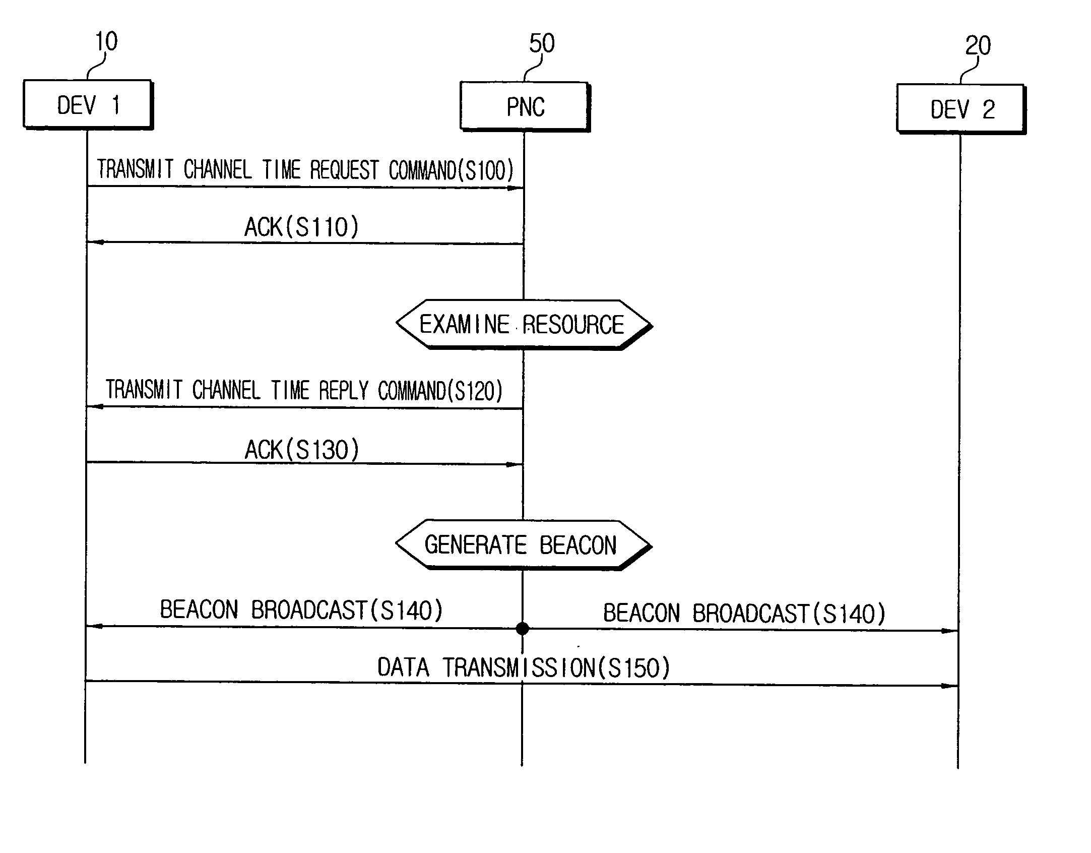
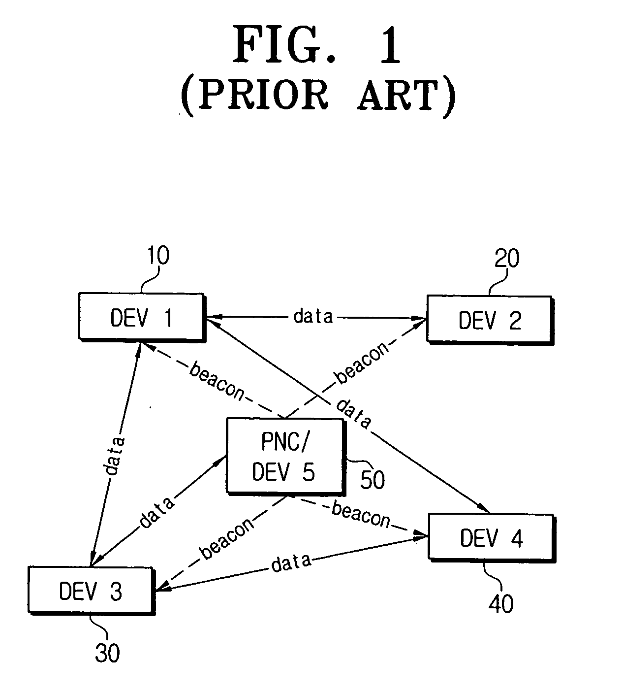
[0028]FIG. 1 is a diagram depicting a configuration of a conventional wireless personal area network (WPAN). Referring to FIG. 1, in the WPAN environment, a plurality of data devices (DEV) 10˜50 configures a piconet, and the DEV 50 in the piconet is a piconet coordinator (hereinafter, refer to as ‘PNC’). The PNC 50 broadcasts a beacon which is a synchronization signal to the other data devices, i.e., DEV110, DEV220, DEV330, DEV440, and synchronizes the data devices linked to the piconet.

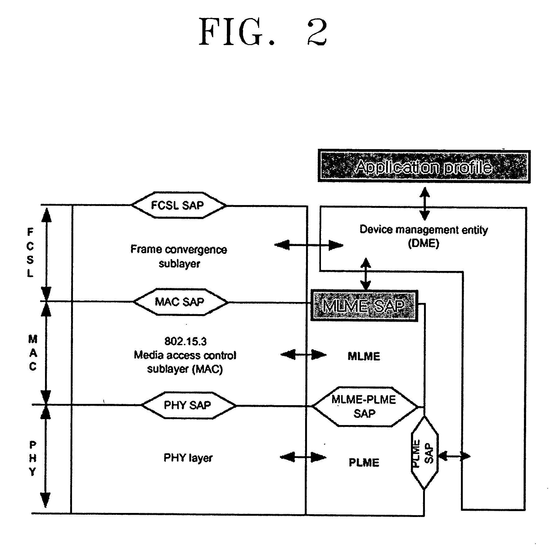
[0029]FIG. 2 is a diagram depicting a configuration of the data devices to provide a channel time allocation method according to the present invention. Referring to FIG. 2, the configuration of the data devices is based on a layer management of an Institute of Electrical and Electronics Engineers, Inc. (IEEE) 802.15.3x standard, and only differs in that an application profile above a Devic...


PUM


Abstract

Disclosed is a channel time allocation method in a high rate WPAN and a wireless system using the same. In the WPAN environment synchronized by a synchronization signal broadcasted from a coordinator, the channel time allocation method includes transmitting a channel time allocation request command corresponding to a property of an application data to be transmitted to the coordinator by any one of devices linked to the WPAN, and the coordinator allocating the channel time, inserting information of the allocated channel time to the synchronization signal, and broadcasting the synchronization signal to the devices. Accordingly, the channel time is allocated to fit for the property of the VBR stream data such as the MPEG-2 video so that the QoS of the VBR stream is provided. At the same time, reliability of the transmission of I frame is enhanced so that success rate of decoding the frame is increased.

Description

CROSS-REFERENCE TO RELATED APPLICATIONS [0001] This application claims the priority of Korean Patent Application No. 2003-30087, filed May 13, 2003 in the Korean Intellectual Property Office, the disclosure of which is incorporated herein by reference. BACKGROUND [0002] 1. Field of the Invention [0003] The present invention relates to a channel time allocation method and a wireless system using the same, and more specifically, to a channel time allocation method for efficiently supporting a variable bit rate (VBR) stream such as MPEG-2 video in a wireless personal area network and a wireless system using the same. [0004] 2. Description of the Related Art [0005] A Wireless Personal Area Network (hereinafter, refer to as “WPAN”) is an implementation of Personal Area Network (PAN) in wireless connection. In contrast to a Local Area Network (LAN) or a Wide Area Network (WAN) that are widely known technologies, the PAN is a network owned by an individual person. That is, devices owned by...

Claims


Application Information

Patent Timeline
Patent Type & Authority Applications(United States)
IPC IPC(8): H04B7/26H04J3/06H04L12/18H04L12/28H04W4/06H04W16/02H04W56/00H04W72/04H04W84/12
CPCH04J3/0638H04N21/43615H04N21/43637H04W72/0446H04W72/0413H04W72/042H04W56/0015H04W72/21H04W72/23H04L12/18H04W84/18H04W72/04
Inventor KIM, YONG-SUKYOON, WON-YONG
Owner SAMSUNG ELECTRONICS CO LTD
Why Eureka
Try Eureka