Image forming apparatus and process cartridge uses in the same

a technology of image forming apparatus and process cartridge, which is applied in the direction of electrographic process apparatus, instruments, optics, etc., can solve the problem of requiring a large installation space, and achieve the effect of reducing a dead spa

Inactive Publication Date: 2005-01-06
FUJIFILM BUSINESS INNOVATION CORP
View PDF12 Cites 19 Cited by
  • Summary
  • Abstract
  • Description
  • Claims
  • Application Information

AI Technical Summary

Benefits of technology

[0014] An object of the present invention is to provide an image forming apparatus capable of reducing a dead space, otherwise, by which even when such a dead space is formed, this dead space can be effectively utilized.
[0016] Although a laser apparatus and / or an LED (Light Emitting Diode) may be employed as the optical writing apparatus, a scanning type laser exposing apparatus is employed. This scanning type laser exposing apparatus may be arranged along a substantially horizontal direction, so that the space defined between the optical writing apparatus and the recording medium storage section arranged along the substantially horizontal direction may be made smaller. As the optical system of the scanning type laser exposing apparatus, there are both an over-field type optical system and an under-field type optical system. In this over-field type optical system, a width of a luminous flux entered into a rotary polygon along a main scanning direction is made wider than a plane width of this rotary polygon. In the under-field type optical system, a width of a luminous flux entered into a rotary polygon along a main scanning direction is made narrower than a plane width of this rotary polygon. In such a case that a plurality of machine sorts of image forming apparatus are wanted to be manufactured in which printing speeds thereof and maximum paper sizes thereof are changed, while image forming apparatus main bodies and the like are commonly utilized, the over-field type optical system is employed when either a high printing speed or a larger maximum paper size is realized, whereas the under-field type optical system is employed when either a low printing speed or a smaller maximum paper size is realized. Generally speaking, since an optical path of an over-field type optical system is long and complex, a larger installation space is required, as compared with that of an under-field type optical system. To the contrary, in such a case that the optical writing apparatus is arranged along the substantially horizontal direction, a lower space of an ejection unit is extended. As a result, if this lower space is made coincident with the storage capacity of the over-field type, then both the over-field type optical system and the under-field type optical system can be properly utilized while the dead space is suppressed to a minimum dead space.
[0018] Also, a control board for controlling drives of the respective components of the image forming apparatus, a network interface board used to constitute a network, or a developer storage vessel for storing thereinto developer is arranged in another space defined between the ejection unit and the optical writing apparatus, sot that this space can be effectively utilized.
[0019] As explained above, in order that the developer storage space is formed at the position higher than the latent image writing position written by the optical writing apparatus, the developer storage space is subdivided into a first developer storage portion arranged at an upper portion thereof, and a second developer storage portion arranged at a lower portion thereof, and also, a window portion is formed between these first and second developer storage portions. As a result, an optical scanning path from the optical writing apparatus can be constituted by this window portion. Also, when such a construction is made that at least a portion of the optical writing apparatus is arranged to be overlapped with respect to the developer storage space along a direction in parallel to an optical axis of incident light to the image carrier, since the incident light optical axial direction of the image forming apparatus can be made short, the better construction of the image forming apparatus can be realized.

Problems solved by technology

Generally speaking, since an optical path of an over-field type optical system is long and complex, a larger installation space is required, as compared with that of an under-field type optical system.

Method used


Image

  • Image forming apparatus and process cartridge uses in the same
  • Image forming apparatus and process cartridge uses in the same
  • Image forming apparatus and process cartridge uses in the same

Examples


first embodiment

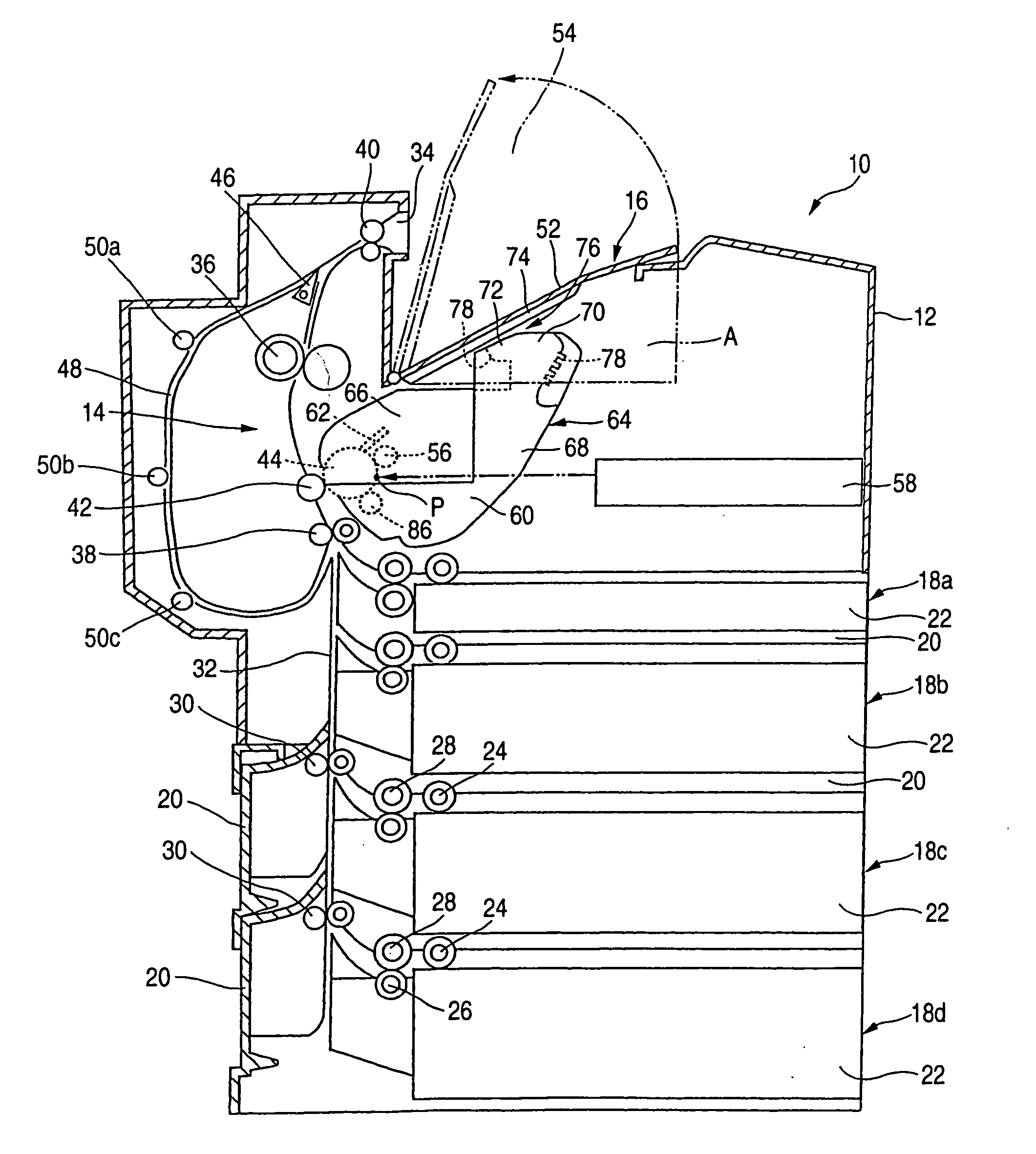
[0050]FIG. 1 schematically shows an image forming apparatus 10 mode of the present invention. The image forming apparatus 10 contains a main body 12 of the image forming apparatus. An image forming section 14 is mounted on this image forming apparatus main body 12. An ejection unit 16 (will be explained later) is provided at an upper portion of this image forming apparatus main body 12, and also, for instance, two stages of paper supply units 18a and 18b are arranged at a lower portion of this image forming apparatus main body 12. Furthermore, two stages of paper supply units 18c and 18d are arranged below the image forming apparatus main body 12, while these paper supply units 18c and 18d are detachably mounted thereon as an optional paper supply unit.

[0051] Each of the paper supply units 18a to 18d owns a paper supply unit main body 20 and a paper supply cassette 22 into which paper is stored. The paper supply cassette 22 is slidably mounted with respect to the paper supply unit ...

second embodiment

[0077] It should be understood that both the control board 136 and the network interface board 138 are arranged in the space A in this second embodiment mode. Alternatively, any one of the control board 136 and the network interface board 138 may be arranged in the space A. Also, both the control board 136 and the network interface board 138 may be collectively mounted on a single board.

[0078]FIG. 5 indicates an image forming apparatus according to a third embodiment mode of the present invention. In this third embodiment mode, a developer storage vessel 142 is arranged in a space “A”. While developer is stored in this developer storage vessel 142, the developer storage vessel 142 is connected to the above-described first developer storage unit 116a, so that the developer can be supplied to the first developer storage portion 116a. In other words, this developer storage vessel 142 constitutes a third developer storage portion, and this developer storage vessel 142 is arranged in the...

third embodiment

[0079] It should also be understood that the developer storage vessel 142 is constructed as a separate member with respect to the process cartridge 64 in this third embodiment mode. Alternatively, as another embodiment mode, the developer storage vessel 42 may be constituted by employing the process cartridge 64 in an integral form. Also, not only the developer storage vessel 142, but also the above-described control board and network interface board may be jointly stored in the space “A”.

[0080] As previously described, in accordance with the present invention, since the latent image writing position is set to be lower than at least a portion of the developer storage space, the space defined between the optical writing apparatus and the paper supply unit can be made narrow, and also the production of the dead space can be suppressed. Also, the control board, the interface board, the developer storage vessel, and the like are arranged between the ejection unit and the optical writing...


PUM


Abstract

A recording medium supplied from any one of paper supply units is printed by an image forming section, and then, the image-formed recording medium is transported via a transport path which is formed along a vertical direction, and thereafter is ejected to an ejection unit which is provided at an upper portion of an image forming apparatus main body. While a developing apparatus of a process cartridge owns a developer storage space, a latent image writing position “P” of an image carrier optically written by an optical writing apparatus is located lower than at least a portion of this developer storage space, and a space defined between the paper supply unit 1 8a and the optical writing apparatus is made small.

Description

[0001] This is a Continuation-in-Part of application Ser. No. 10 / 226,305 filed Aug. 23, 2002, which claims the benefit of Japanese Patent Application No. JP 2001-388372 filed Dec. 20, 2001, and is a Continuation-in-Part of application Ser. No. 10 / 366,322 filed Feb. 14, 2003, which claims the benefit of Japanese Patent Application No. JP 2002-261911 filed Sep. 6, 2002. The entire disclosure of the prior application is hereby incorporated by reference herein in its entirety.BACKGROUND OF THE INVENTION [0002] 1. Field of Invention [0003] The present invention is related to an electro-photographic type image forming apparatus. [0004] 2. Description of Related Art [0005] As this sort of image forming apparatus, such an image forming apparatus is known in which while a recording medium is transported along a substantially vertical direction, an image is formed on this transported recording medium, and then, the recording medium on which the image has been formed is ejected to an ejection ...

Claims


Application Information

Patent Timeline
Patent Type & Authority Applications(United States)
IPC IPC(8): G03G15/00
CPCG03G15/04072G03G21/1821G03G21/1609
Inventor SAITO, MANABUAMAMOTO, HIDEKAZUSAIKI, ATSUNAABE, TAKAHARU
Owner FUJIFILM BUSINESS INNOVATION CORP
Why Eureka
Try Eureka