Adapter for multi-element contact-probe

a multi-element, contact-probe technology, applied in the field of disposable adapters, can solve the problems of affecting the energy or substance transfer between the active element and the target surface, the array structure that ensures the determined contact force of each of the array elements is quite complex and expensive, and the fixture is expensive and prohibits disposable us

Inactive Publication Date: 2005-01-06
AVIRAM DAVID +1
View PDF4 Cites 16 Cited by
  • Summary
  • Abstract
  • Description
  • Claims
  • Application Information

AI Technical Summary

Benefits of technology

[0013] An Adaptor structure shall mean a self-supporting structure adapted to be mounted on a said Contact probe or a said Target surface, consisting of a frame structure, which supports a sheet-structure. The Adaptor structure when used in alignment with a Contact probe will form a physical buffer between the Contact probe front-end elements and the Target surface while substantially maintaining the functionality of the said Contact probe.
[0017] An Elastically coupling shall mean joining means or material surrounding the More rigid constituents, allowing locally confined deformation of said Sheet structure (preferably elastic) substantially in the normal orientation by enabling displacement of the corresponding More rigid constituents upon exertion of a local force. Elastically coupling may be implemented at various methods, as non limiting examples: introducing non-through fractures around More rigid constituents, reduced material thickness in between More rigid constituents, use of highly elastic or highly flexible materials and by controlled polymerization of joining zones.
[0021] The present invention provides a sheet structure wherein the More rigid constituents are in alignment with a Contact probe front end Elements to transfer the force exerted by each probe front end Element to the corresponding point on the Target surface. The More rigid constituents are joined together to form a Sheet structure. The said Sheet structure is adapted to provide a physical buffer between the probe front end Elements and Target surface, preferably simple enough for disposable use. It further suggests, that said More rigid constituents are joined together to form a Sheet structure by Elastically coupling that allow each of the More rigid constituents to be displaced in correspondence with its adjacent elements at a substantially normal orientation to the Sheet structure, while minimizing transversal stress coupling among the More rigid constituent elements, thus significantly reducing the influence on neighboring elements contact force. Apart of transferring force the More rigid constituents are adapted to transfer the appropriate energy form or Substance to allow probe functionality.
[0033] The present invention provides also a method for buffering between a Contact probe and a surface Target by utilizing a removable mediating member in alignment with Contact probe Elements enabling transfer of contact force while maintaining probe functionality for protecting either the probe or the Target surface from contamination or wear.

Problems solved by technology

As known to any professional in the field, the lack of contact force adversely affects the energy or Substance transfer to and from the active element and the Target surface.
An Array structure that ensures determined contact force of each of the Array elements is quite complex and expensive.
As an example “bed of nails” fixture consists plurality of spring loaded pin contacts to allow each contact to engage at different position while exerting the required force, resulting in an expensive fixture prohibiting disposable use.
Another example is the medical devices such as ultrasound probes, bioimpedance probes, transdermal skin treatment devices which require a very high-pressure to create such a high internal object stress (pressure) causing deformation of Target surface to ensure each element contact force, resulting in low patient compliance.
When probe front-end surface comes into contact with the Target surface it wears and gets contaminated by the Target surface, requiring maintenance, cleaning and in some applications sterilization, which are costly procedures.
In some medical applications it is prohibitive to reuse the probe.

Method used


Image

  • Adapter for multi-element contact-probe
  • Adapter for multi-element contact-probe
  • Adapter for multi-element contact-probe

Examples


Embodiment Construction

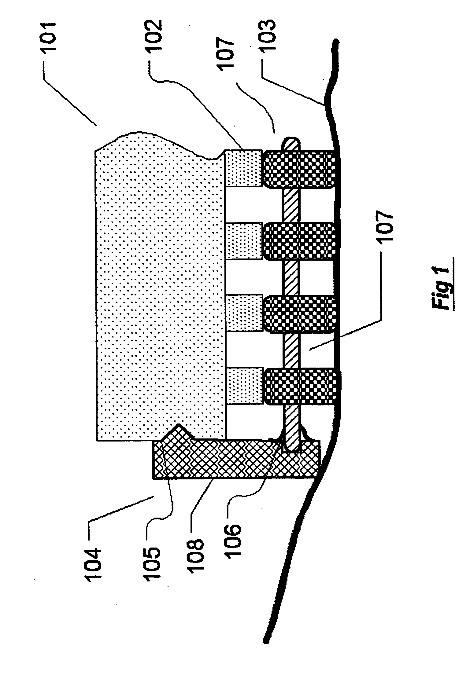
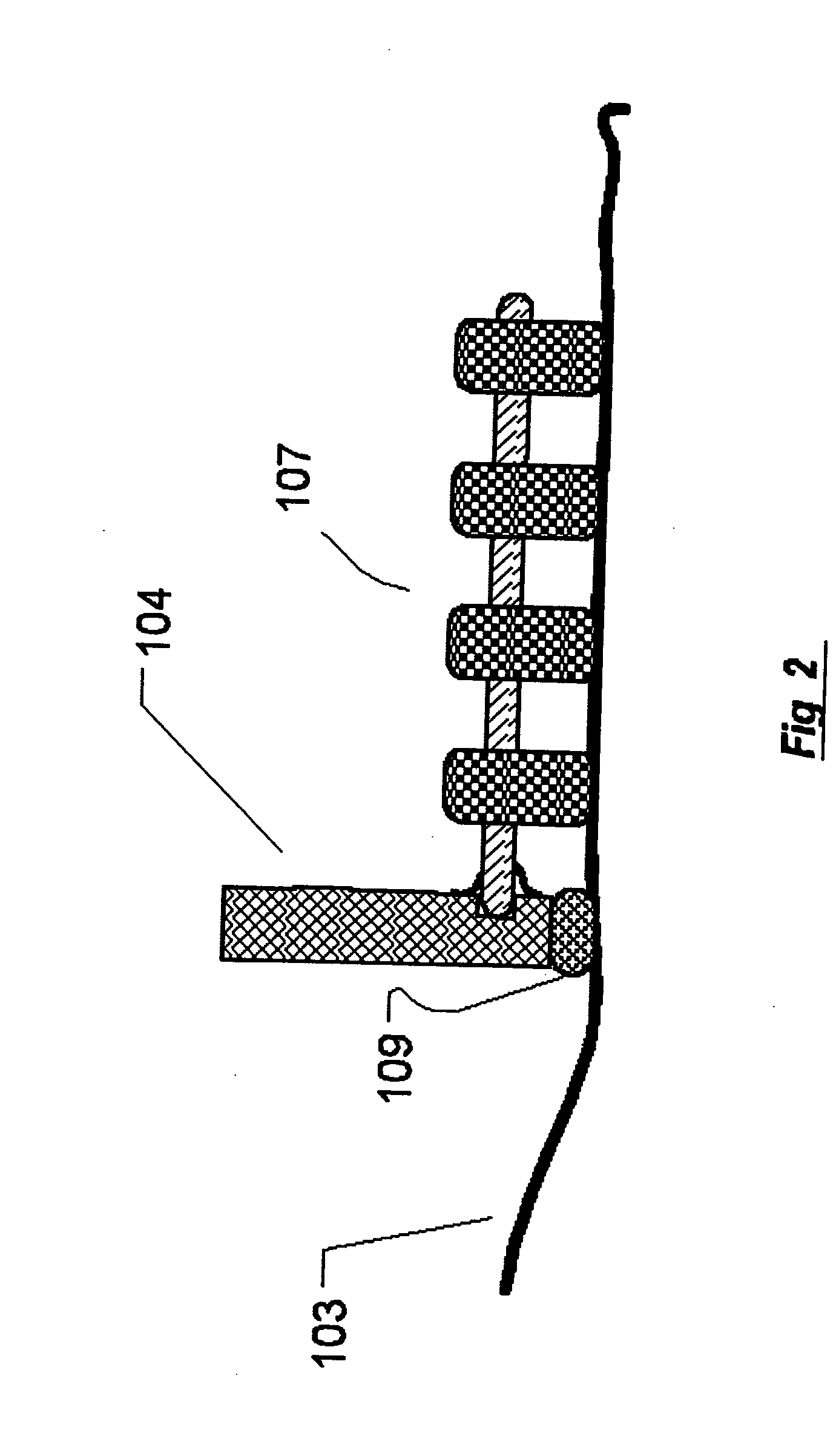
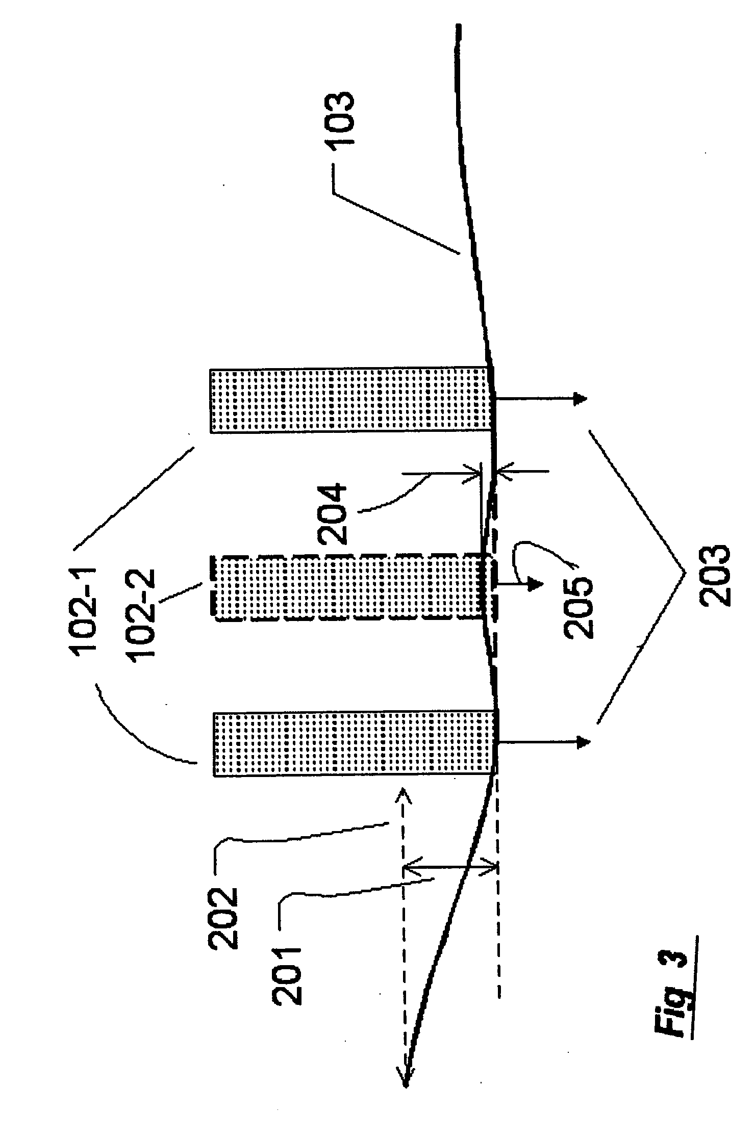
[0048] Reference is made to FIG. 1 showing a partial view of a Contact probe, Adaptor structure and Target surface. A Contact probe 101 consisting of at least some active Elements 102 attached to a Target surface 103 through an Adaptor structure 104. The Adaptor structure 104 is adapted to be mounted on the Contact probe 101 in alignment with its active Elements by fastening means 105 which may be implemented in various ways such as mechanical clamps, mechanical fasteners, magnetic fastener, pin guiders and locking mechanisms known to any professional person in the field. The Adaptor structure 104 basically consists of a frame structure 108 made of a rigid material, preferably injected plastic material compatible with the specific application, to provide a support structure to which a Sheet structure 101 is attached by common means 108, such as: ultrasound welding, adhesion, mechanical fastening or being molded as an integral part of the frame, known to any professional person in th...


PUM

PropertyMeasurementUnit
contact forceaaaaaaaaaa
flexibleaaaaaaaaaa
Adaptor structureaaaaaaaaaa

Abstract

The disclosed invention describes an Adaptor structure, used in conjunction with a multi-element contact-probe, for protecting the probe elements and the Target surface from wearing and contamination, while maintaining probe functionality including the probe elements contact force exerted on the corresponding Target surface points. The provided Adaptor structure is removable and suitable for disposable applications. The invention constitutes also a method in which the mediating Adaptor structure physically buffers between the Contact probe front-end and Target surface. Further the invention constitutes also a kit comprising at least one Contact probe and at least one Adaptor structure.

Description

[0001] This application claims the benefit of priority from IL Patent application No. 156789, filed Jul. 6, 2003. FIELD OF THE INVENTION [0002] This present invention relates to disposable adaptors for intermediating between multi elements contact-probe and a Target surface, involving transfer of energy, Substance or force across the adaptor thickness to or from the Target surface, for protecting the probe or the Target surface, both or either one. PRIOR ART OF RELEVANCE [0003] The following U.S. Pat. No.: 6,489,003 to 3M; U.S. Pat. No. 6,508,785 to Altea; and U.S. Pat. Nos. 6,148,232 and 5,983,135 both to Transpharma include prior art of relevance. BACKGROUND OF THE INVENTION [0004] Contact array probes are widely used in industry and medical applications. In the electronics industry Contact probes are used in variety of testing systems usually by utilizing fixtures called “bed of nails” to provide electrical contacts with test pads on boards. Likewise probes of bioelectric mapping...

Claims


Application Information

Patent Timeline
Patent Type & Authority Applications(United States)
IPC IPC(8): A61F7/00A61NA61N1/04A61N5/06A61N7/00C12M1/34
CPCA61F7/00A61N1/0412A61N2005/0645A61N1/0476A61N7/00A61N1/0428
Inventor AVIRAM, DAVIDAVRAHAMI, ZOHAR
Owner AVIRAM DAVID
Why Eureka
Try Eureka