

Amplified system for determining parameters of a patient
- Summary
- Abstract
- Description
- Claims
- Application Information
AI Technical Summary
Benefits of technology
Problems solved by technology
Method used
Image


Examples
Embodiment Construction
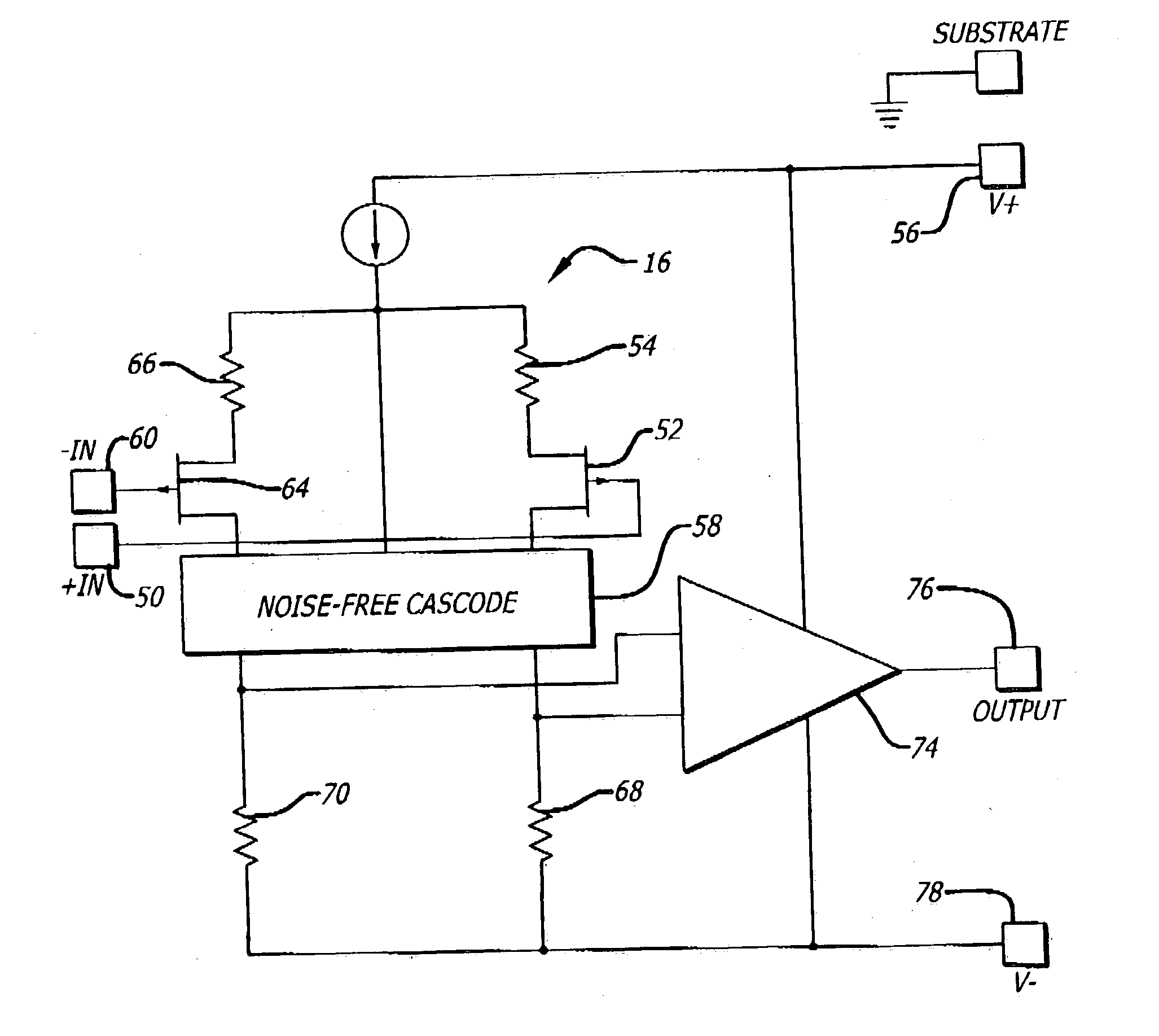
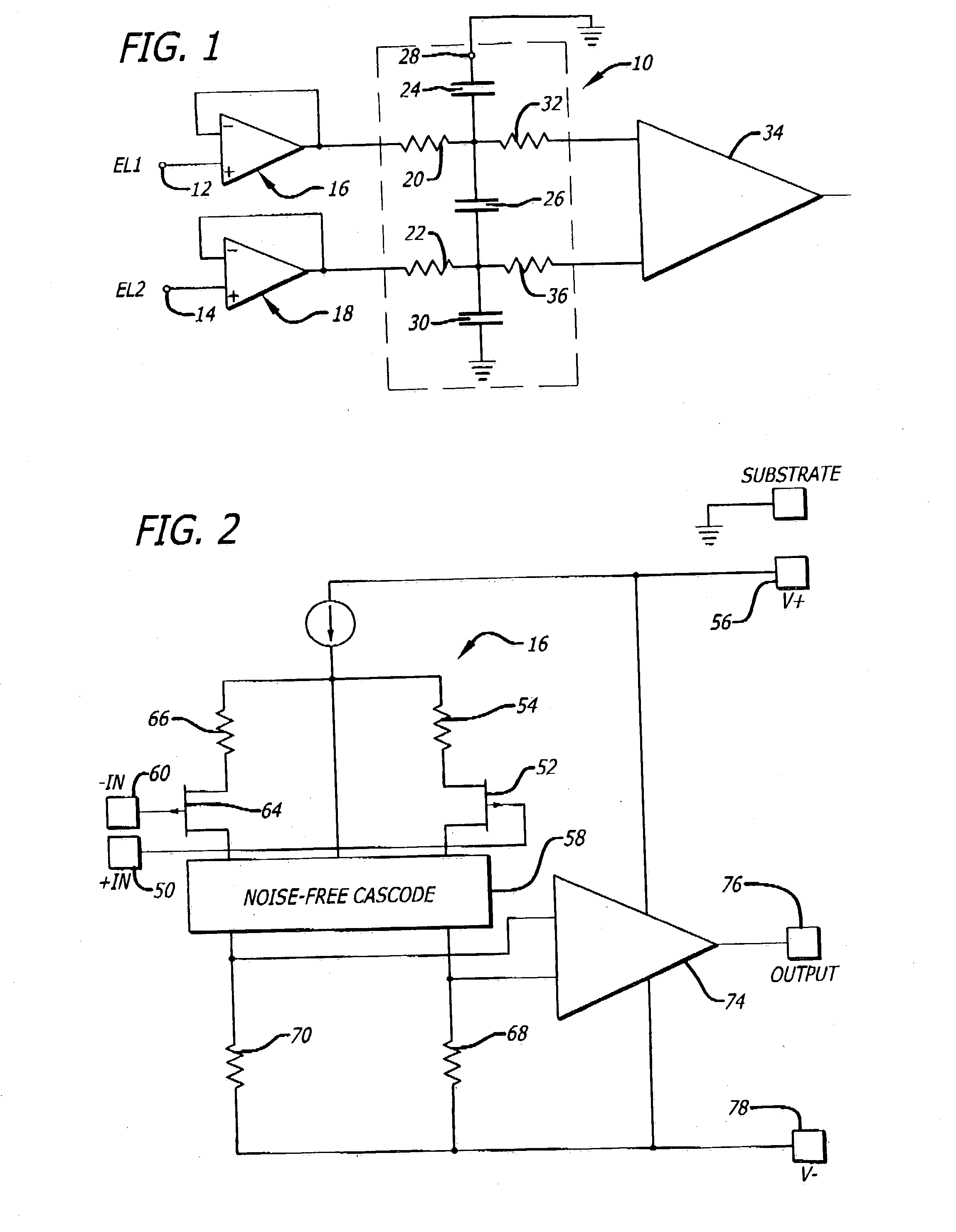
[0009] This invention provides an amplifier system which provides an amplification of the signals from any one of a plurality of organs in a patient's body regardless of the organ to which the amplifier system is coupled. The amplifier system includes an amplifier which is operative to amplify the signals from any selected one of the organs in the patient's body without any loss in the signal strength and without any changes in the characteristics of the signals.
[0010] In accordance with a preferred embodiment of the invention, an electrode is attached at a selective position to a patent's body to provide signals representative of the patient's parameters (e.g., electrocardiogram) at this position. The electrode signal may be in the order of microvolts or millivolts. Depending upon the characteristics of the patient's skin, the electrode-skin impedances may vary to approximately 200 kilohms. The electrode signals pass to an amplifier having an input impedance (e.g., 1015 ohms) appr...
PUM
 Abstract
Description
Claims
Application Information