Voice activated diagnostic imaging control system

a control system and voice technology, applied in the field of medical imaging, can solve the problems of limited mobility and accessibility of the user interface used in diagnostic imaging, limited range of motion of the interface, and difficulty in initial location of the remote user interface in the examination room

Inactive Publication Date: 2005-01-06
GENERAL ELECTRIC CO
View PDF3 Cites 18 Cited by
  • Summary
  • Abstract
  • Description
  • Claims
  • Application Information

AI Technical Summary

Benefits of technology

[0008] In one aspect, a medical examination suite is provided. The suite comprises an exam room having a microphone and at least a portion of a medical imaging system therein. A microphone sensitivity zone is located in the exam room. The suite may further comprise a control room adjacent the exam room and having a video monitor and controls for the imaging system therein, and an equipment room having a processor, e.g., a computer therein. The computer is coupled, e.g., via video processing and display equipment, to the microphone and to the video monitor and controls for the imaging system.
[0009] In another aspect, a voice activated control subsystem for a medical imaging system is provided. The control subsystem comprises an audio microphone configured to be positioned for receiving audio input from an operator, an audio amplifier for receiving audio signals generated by the microphone, and an audio signal processor coupled to the amplifier for processing amplified audio si

Problems solved by technology

User interfaces used in diagnostic imaging, however, have limited mobility and accessibility.
For example, typical user interfaces consist of knobs, buttons, switches and displays mounted in a specific location, or the interface range of motion is limited by electrical cables.
The remote user interface, however, can be difficult to initially locate in a

Method used


Image

  • Voice activated diagnostic imaging control system
  • Voice activated diagnostic imaging control system
  • Voice activated diagnostic imaging control system

Examples


Embodiment Construction

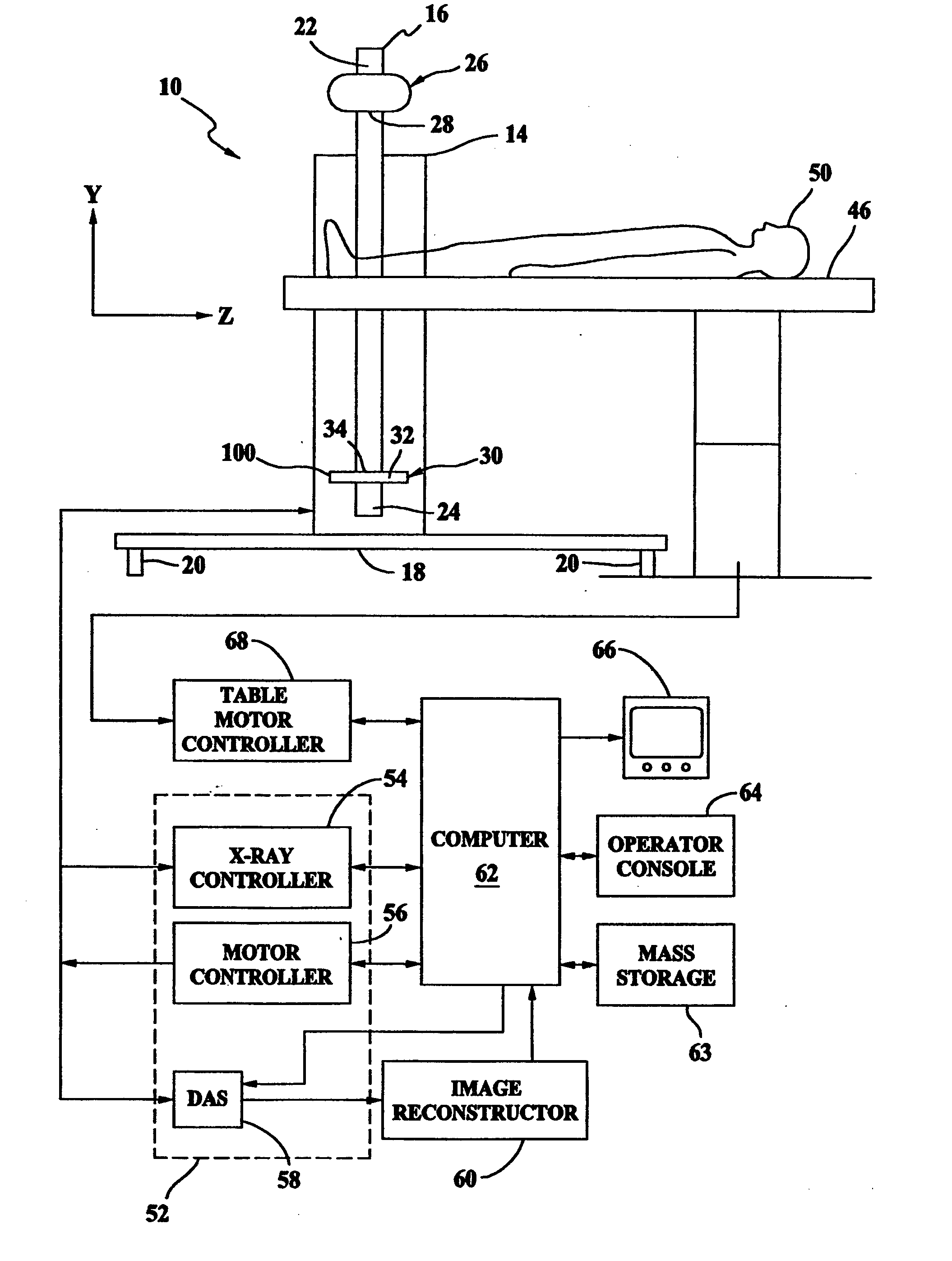
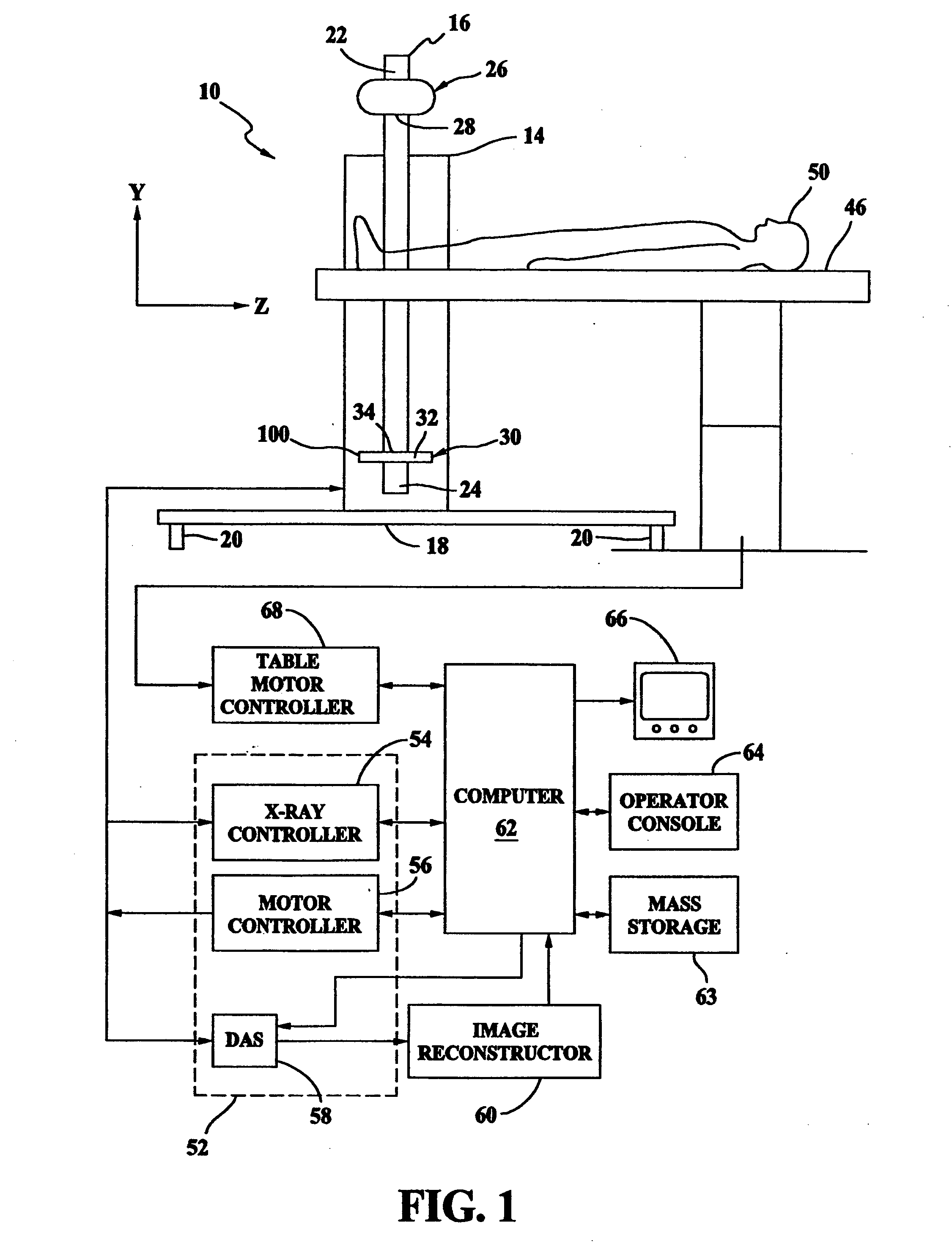
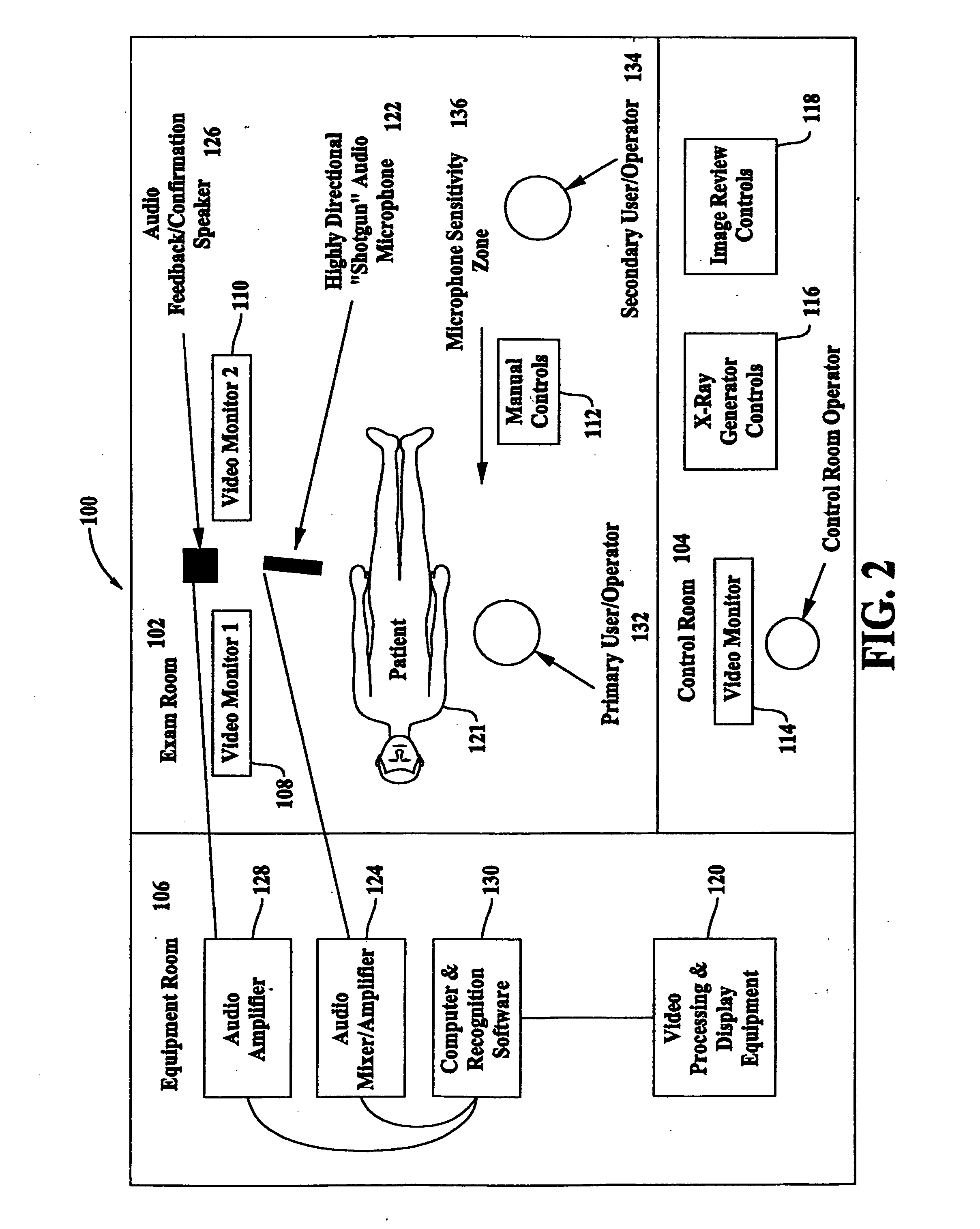
[0013] A voice activated user interface to control diagnostic imaging equipment is described herein. Rather than navigate a series of buttons, switches, and joysticks, an operator can speak a designated command for a desired operation. In addition, the operator can obtain feedback from the system through computer-generated speech. For example, the operator can request previous X-ray exposure parameters (kV, mAs), and the system then communicates these numbers, via an audio signal, back to the operator without the operator having to consult the local display of these numbers.

[0014] Although the interface is described herein in the context of an X-ray system, the interface is not limited to practice with X-ray systems and can be utilized in many different imaging modalities. For example, the interface can be used in connection with computed tomography, magnetic resonance, positron emission tomography, ultrasound, and other imaging modalities.

[0015] The interface, in an example embod...


PUM


Abstract

A medical examination suite is described. In one example embodiment, the suite comprises an exam room having a microphone and at least a portion of a medical imaging system therein. A microphone sensitivity zone is located in the exam room. The suite further comprises a control room adjacent the exam room and having a video monitor and controls for the imaging system therein, and an equipment room having a computer therein. The computer is coupled to the microphone and to the video monitor and controls for the imaging system.

Description

BACKGROUND OF THE INVENTION [0001] This invention relates generally to medical imaging, and more particularly, to voice activated controls for use in connection with medical imaging systems. [0002] Known medical diagnostic imaging systems require an operator (e.g., a technologist, surgeon, cardiologist) to control operation of sophisticated systems (e.g., X-ray system, computed tomography system, magnetic resonance system) as well as tend to needs of a patient. As diagnostic imaging systems and associated procedures become more sophisticated, the operator directs increased attention to the configuration and control of the imaging system and auxiliary equipment (e.g., tables, injectors, patient monitors). [0003] In addition, interventional procedures can now be performed on a patient while performing a medical imaging procedure. Specifically, when performing an interventional procedure, an area of interest can be actively imaged. In such interventional procedures, a primary operator ...

Claims


Application Information

Patent Timeline
IPC IPC(8): G01R33/28A61B5/00A61B5/055A61B6/00A61B6/03A61B8/00A61B19/00G06F3/16G06F19/00G10L15/00G10L15/28H04R1/32
CPCA61B5/055A61B5/7475A61B6/00A61B6/032A61B6/467A61B6/548G06F3/16G06F19/321G06F19/3406A61B6/4423A61B8/467G16H40/63G16H30/20
Inventor JOHNSON, MARK A.CHASE, MAUREEN L.
Owner GENERAL ELECTRIC CO
Why Eureka
Try Eureka