
Traffic management using in-band flow control and multiple-rate traffic shaping

a traffic management and flow control technology, applied in the field of network-based communication systems, can solve the problems of not meeting the requirements of many high channel count (hcc) packet-based applications, the current spi-3 interface standard falls far short of this goal, and the standard supports a maximum of 256 mphys, etc., to achieve the effect of improving the detection of backpressur

Active Publication Date: 2005-01-06
INTEL CORP
View PDF3 Cites 51 Cited by
  • Summary
  • Abstract
  • Description
  • Claims
  • Application Information

AI Technical Summary

Benefits of technology

The present invention meets the above-noted need by providing in a first aspect of the invention an in-band flow control mechanism which facilitates the delivery of backpressure information from a physical layer device to a link layer device in a communication system. Another aspect of the invention relates to the provision of traffic shaping responsive to a flow control message received in a link layer device from a physical layer device.
Advantageously, the invention provides improved detection of backpressure, particularly for HCC packet-based applications, and can be implemented using an SPI-3 interface or other standard interface while overcoming the above-noted limitations of such standard interfaces. It also provides improved traffic shaping techniques, such as multiple-rate shaping, responsive to detected backpressure.

Problems solved by technology

A significant problem that can arise when utilizing the SPI-3 interface standard is that the standard supports a maximum of only 256 MPHYs.
Although this is substantially more than other similar interfaces, such as POS-2, it nonetheless fails to meet the requirements of many high channel count (HCC) packet-based applications.
Unfortunately, the current SPI-3 interface standard falls far short of this goal.

Method used


Image

  • Traffic management using in-band flow control and multiple-rate traffic shaping
  • Traffic management using in-band flow control and multiple-rate traffic shaping
  • Traffic management using in-band flow control and multiple-rate traffic shaping

Examples


Embodiment Construction

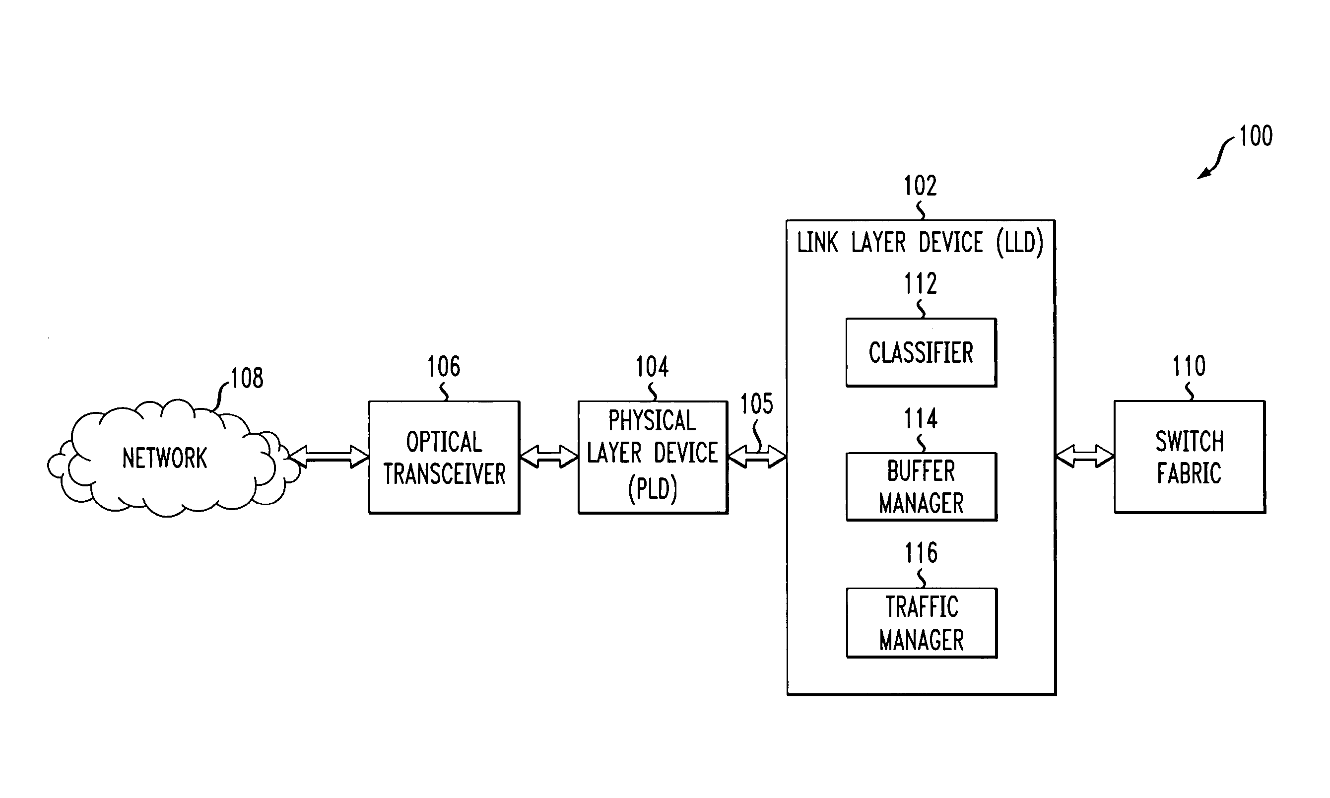
The invention will be illustrated herein in conjunction with an exemplary network-based communication system which includes a link layer device, a physical layer device and other elements configured in a particular manner. It should be understood, however, that the invention is more generally applicable to any system in which it is desirable to provide improved traffic shaping through the use of at least one of in-band flow control and multiple-rate traffic shaping as described herein.

The term “in-band” as used herein is intended to include, by way of example and without limitation, an arrangement in which additional information is transmitted utilizing an existing standard interface, such as an SPI-3 or other similar interface, between a link layer device and a physical layer device, where the additional information is of a type not normally associated with the standard interface.

A “link layer device” or LLD as the term is used herein refers generally to a network processor or...


PUM


Abstract

Backpressure information is communicated from a physical layer device to a link layer device in a communication system by generating a flow control message in the physical layer device responsive to a detected condition relating to at least a given one of a plurality of queues of the physical layer device, and transmitting the flow control message from the physical layer device to the link layer device. The flow control message may comprises backpressure information associated with a given egress queue of the physical layer device and is transmitted from the physical layer device to the link layer device as an in-band message over an interface between the physical layer device and the link layer device. Multiple-rate traffic shaping or other types of traffic shaping may be provided responsive to the flow control message.

Description

FIELD OF THE INVENTION The present invention relates generally to network-based communication systems, and more particularly to traffic management techniques for use in a communication system in which a physical layer device communicates with a link layer device. BACKGROUND OF THE INVENTION A network processor is one example of what is more generally referred to herein as a link layer device. Such link layer devices, which can be used to implement packet-based protocols such as Internet Protocol (IP) and Asynchronous Transfer Mode (ATM), are also commonly known as Layer-3 (L3) devices in accordance with the well-known Open System Interconnect (OSI) model. Communication between a physical layer device and a network processor or other type of link layer device may be implemented in accordance with an interface standard, such as the SPI-3 interface standard described in Implementation Agreement OIF-SPI3-0 1.0, “System Packet Interface Level 3 (SPI-3): OC-48 System Interface for Phys...

Claims


Application Information

Patent Timeline
Patent Type & Authority Applications(United States)
IPC IPC(8): G06F15/16H04L12/56
CPCH04L47/10
Inventor GRANT, KEVIN S.SIMKINS, MARK BENJAMINSONNIER, DAVID P.
Owner INTEL CORP
Learn More