Plant and process for liquefying natural gas

a technology of liquefied natural gas and plant, which is applied in the direction of liquefaction, refrigeration machines, sorption machines, etc., can solve the problems of limited capacity of propane compressors, limited capacity of liquefaction plants, and insufficient suction and discharge outlets of propane compressors in parallel

Inactive Publication Date: 2005-01-13
TOTAL PUTEAUX FR
View PDF6 Cites 45 Cited by
  • Summary
  • Abstract
  • Description
  • Claims
  • Application Information

AI Technical Summary

Problems solved by technology

Such a plant, while it allows for a 40 to 60% increase of liquefaction capacity, still suffers from drawbacks.
The liquefaction plant is still limited by the capacity of the propane compressor used in the pre-cooling refrigerant circuit.
The limited capacity of the propane compressor is still a problem for other usual plants.
Solving this problem of limited capacity by the use of a pair of propane compressors in parallel on the same suction and discharge outlets is not satisfactory, since imbalanced load sharing and flow instability can then occur.

Method used


Image

  • Plant and process for liquefying natural gas
  • Plant and process for liquefying natural gas
  • Plant and process for liquefying natural gas

Examples


Embodiment Construction

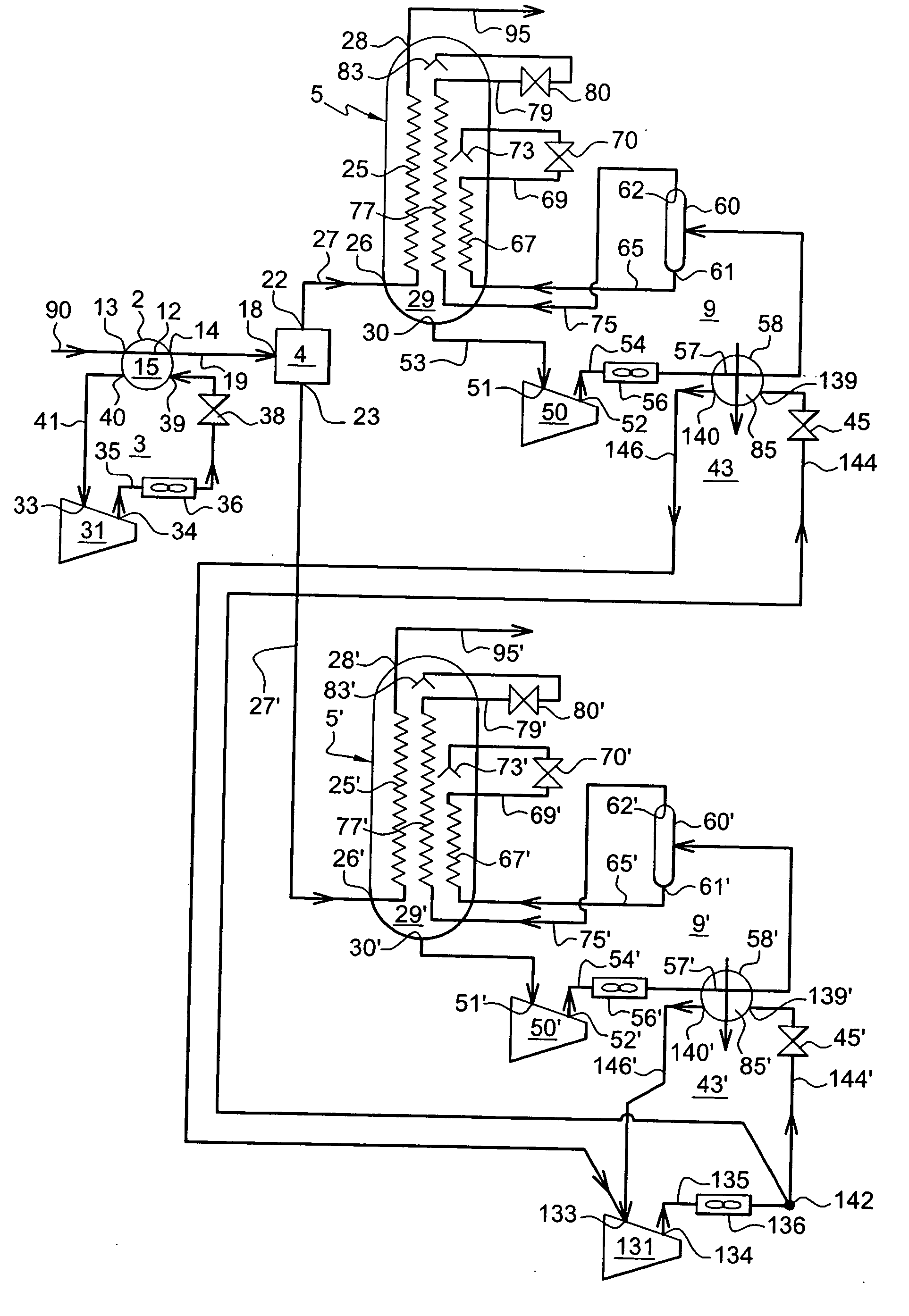
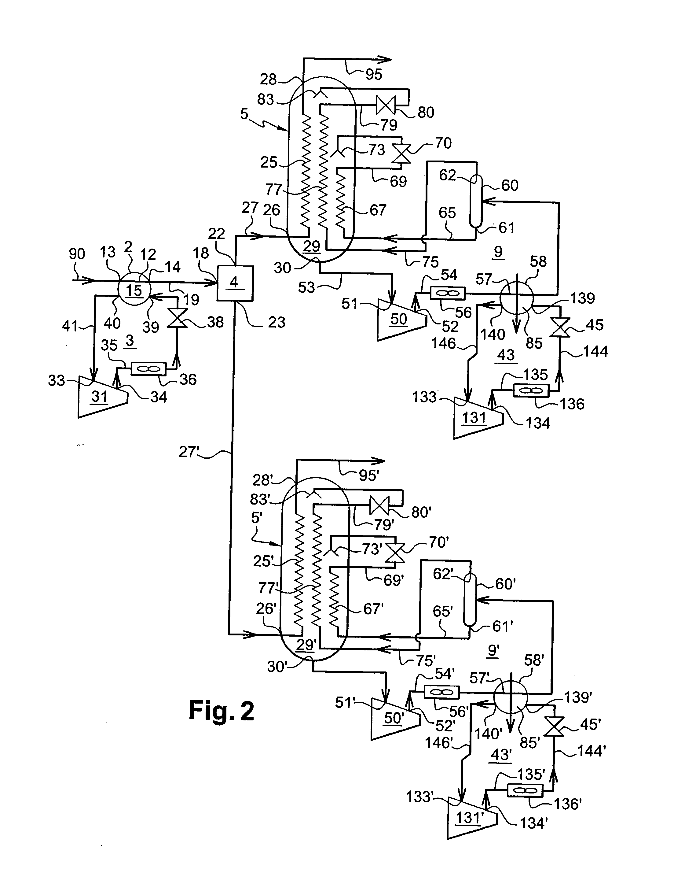
[0060] Reference is made to FIG. 1. The plant for liquefying natural gas according to the present invention comprises one natural gas pre-cooling heat exchanger 2, a pre-cooling refrigerant circuit 3, one main heat exchanger 5, and one main refrigerant circuit 9.

[0061] The natural gas pre-cooling heat exchanger 2 has a hot side in the form of tube 12 that has an inlet 13 for natural gas and an outlet 14 for cooled natural gas. The tube 12 is arranged in the cold side or shell side 15 of the natural gas pre-cooling heat exchanger 2.

[0062] The liquefaction heat exchanger 5 comprises a first hot side 25 having one inlet 26. The inlet 26 of the first hot side 25 is connected to the outlet 14 of the heat exchanger 2, by means of conduit 27. The hot side 25 has an outlet 28 at the top of the liquefaction heat exchanger 5 for liquefied natural gas. The first hot side 25 is located in the cold side 29 of the liquefaction heat exchanger 5, which cold side 29 has an outlet 30.

[0063] The pr...


PUM


Abstract

The invention relates to novel plant and process for producing liquefied natural gas. The plant of the invention is of the type that comprises one natural gas pre-cooling heat exchanger having an inlet for natural gas and an outlet for cooled natural gas, optionally a distributor having an inlet connected to the outlet for cooled natural gas and having one or more outlets, and one or more main heat exchangers each comprising a first hot side having one inlet connected to one outlet of the distributor and an outlet for liquefied natural gas, which plant further comprises a pre-cooling refrigerant circuit for removing heat from the natural gas in the natural gas pre-cooling heat exchanger, and one or more main refrigerant circuits for removing heat from natural gas flowing through the first hot side of the corresponding main heat exchanger. The invention is based on the use of separate pre-cooling circuits: one for the pre-cooling of the natural gas and one for the pre-cooling of the main refrigerant.

Description

FIELD OF THE INVENTION [0001] The invention relates to novel plant and process for producing liquefied natural gas. The plant of the invention is of the type that comprises one natural gas pre-cooling heat exchanger having an inlet for natural gas and an outlet for cooled natural gas, optionally a distributor having an inlet connected to the outlet for cooled natural gas and having one or more outlets, and one or more main heat exchangers each comprising a first hot side having one inlet connected to one outlet of the distributor and an outlet for liquefied natural gas, which plant further comprises a pre-cooling refrigerant circuit for removing heat from the natural gas in the natural gas pre-cooling heat exchanger, and one or more main refrigerant circuits for removing heat from natural gas flowing through the first hot side of the corresponding main heat exchanger. BACKGROUND OF THE INVENTION [0002] U.S. Pat. No. 4,274,849 and EP-A-0281821 disclose a process for liquefying a gas ...

Claims


Application Information

Patent Timeline
Patent Type & Authority Applications(United States)
IPC IPC(8): F25J1/02
CPCF25J1/0022F25J2270/906F25J1/0055F25J1/0268F25J1/0271F25J1/0282F25J1/0283F25J1/0284F25J1/0289F25J1/029F25J1/0292F25J2220/64F25J2240/82F25J1/0212F25J1/0214F25J1/0227F25J1/0242F25J1/0216F25J2270/60F25J1/0052F25J2270/12F25J1/0262
Inventor LE METAIS, MARC
Owner TOTAL PUTEAUX FR
Why Eureka
Try Eureka