

Electrical metallic tube, coupling, and connector apparatus and method
- Summary
- Abstract
- Description
- Claims
- Application Information
AI Technical Summary
Benefits of technology
Problems solved by technology
Method used
Image

Examples
Embodiment Construction
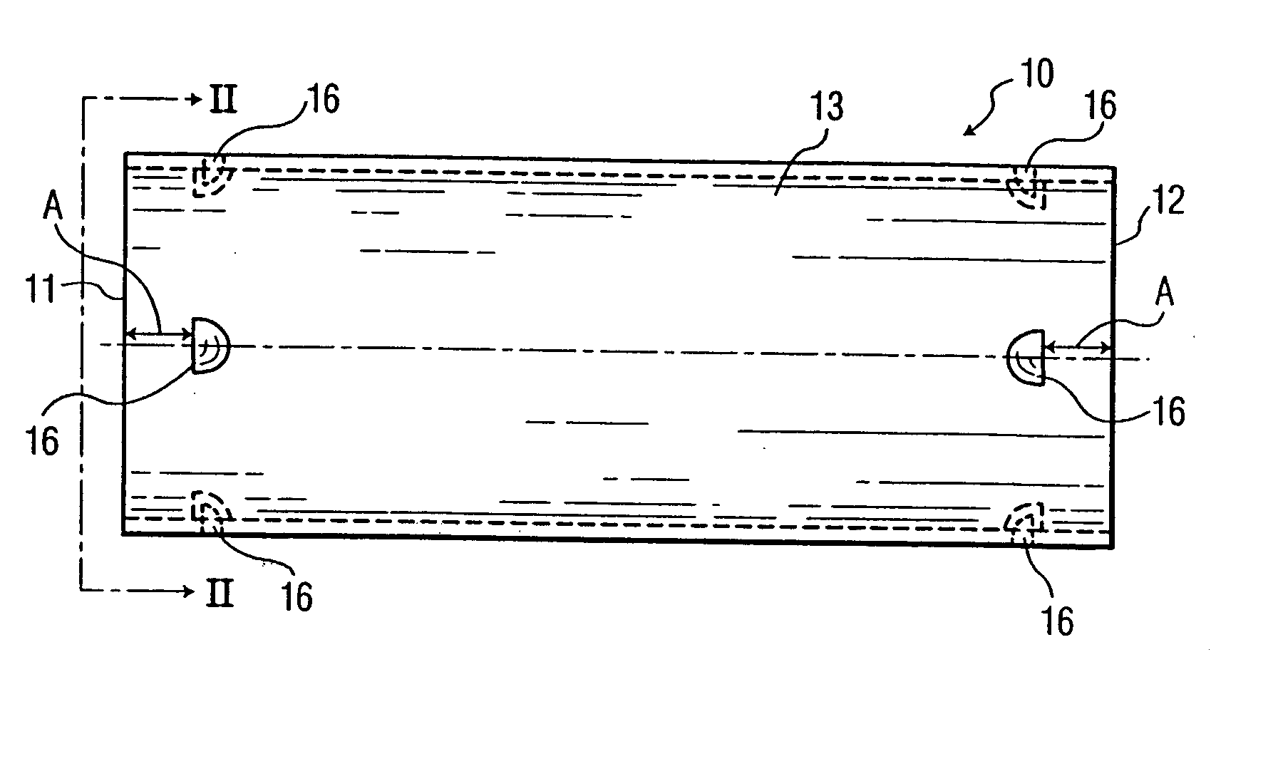
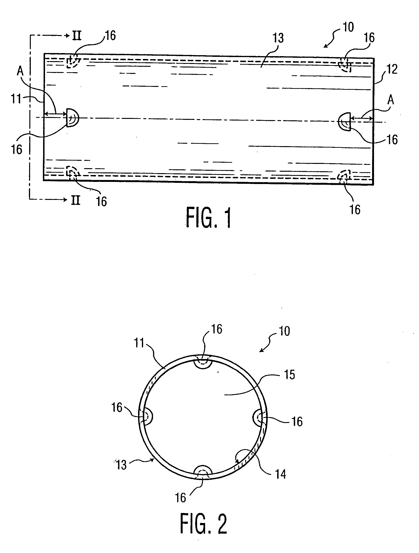
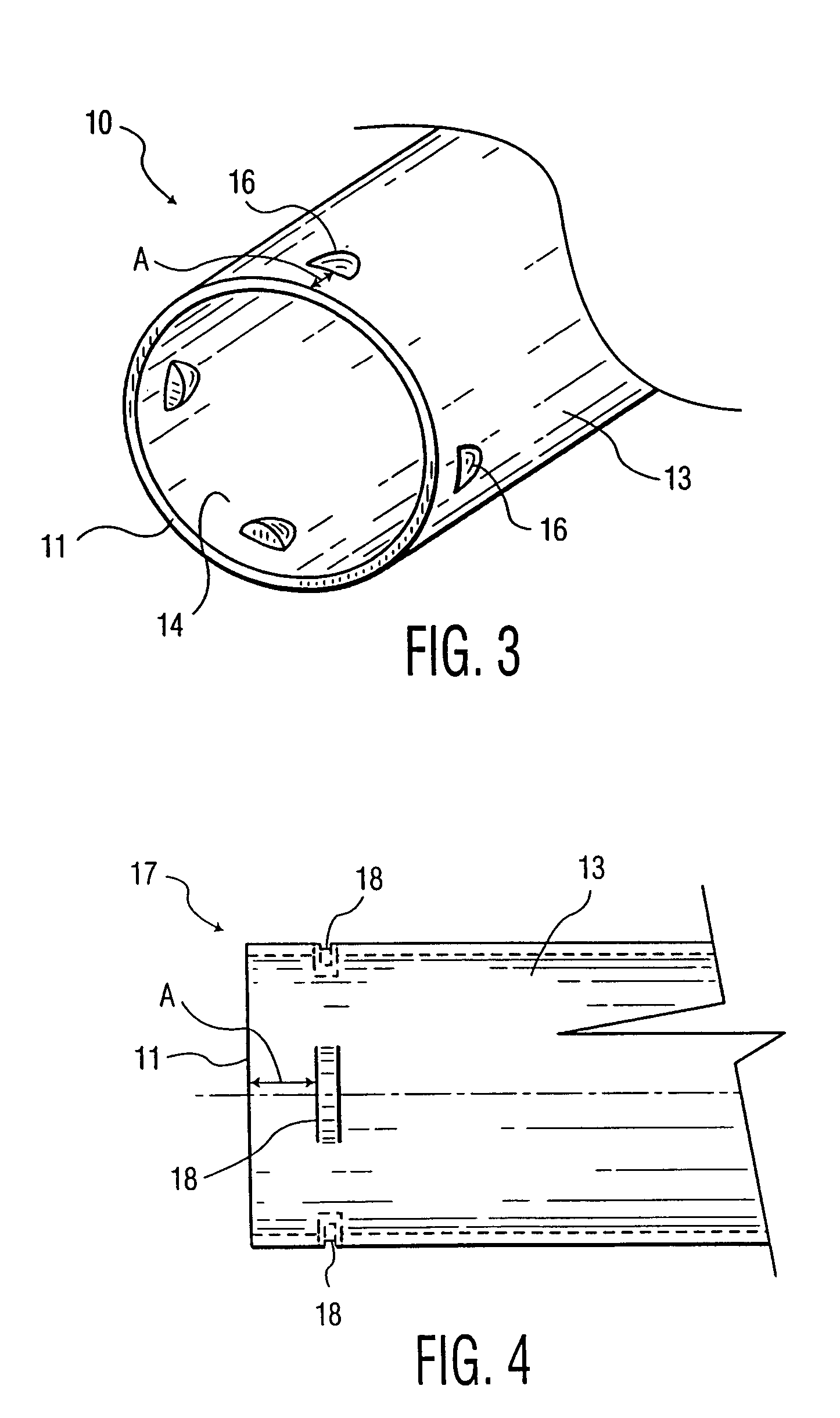
[0045] Referring to FIGS. 1-3, an embodiment of a length of EMT is illustrated according to the present invention. EMT 10 has tubular shape and a circular cross-sectional profile. EMT 10 can be constructed of steel, alloys, aluminum, or any other metal or material capable of carrying electricity. EMT 10 has an outer surface 13 and an inner surface 14. EMT 10 has EMT first end 11 and EMT second end 12. Inner surface 14 forms EMT cavity 15 extending through the length of EMT 10 for holding wire.
[0046] EMT 10 further comprises indentations, in the form of D-shaped dimples 16, at both EMT first end 11 and EMT second end 12. Each of the D-shaped dimples 16 are adapted to receive and engage a corresponding barb 25 of sleeve device 20 (FIGS. 6 and 7). EMT 10 comprises four D-shaped dimples 16 circumferentially located around each of its ends 11, 12. D-shaped dimples 16 are formed in outer surface 13 by punching or pressing and preferably have a depth of approximately one-eighth inch. EMT ...
PUM
 Abstract
Description
Claims
Application Information