Method and apparatus for instrumental analysis in remote locations

a technology for cathodic protection and remote locations, applied in the direction of measuring devices, scientific instruments, instruments, etc., can solve the problems of measuring the degree of cathodic protection in a remote or concealed area, causing anodization, and metal structures immersed in aqueous electrolytic environments susceptible to corrosion

Inactive Publication Date: 2005-01-13
G I RUSSELL
View PDF23 Cites 29 Cited by
  • Summary
  • Abstract
  • Description
  • Claims
  • Application Information

AI Technical Summary

Benefits of technology

[0020] In yet another broad aspect, the present invention provides a system for mitigating stray current discharging to or being discharged from a metal structure disposed in an electrolytic environment comprising: a means for predetermining a location of stray current discharge, a means for mitigating stray current discharge, and a passage for receiving movement of the means for mitigating to effect positioning of the means for mitigating at the predetermined location.

Problems solved by technology

Metal structures immersed in aqueous electrolytic environments are susceptible to corrosion.
Corrosion occurs when the current discharges from the metal surface into the electrolyte, thereby creating anodic areas.
However, such measurements do not provide an accurate indication of the degree of cathodic protection in a remote or concealed area, such as within a crevice.
Conventional auto-potential control of impressed current sources alone, therefore, is insufficient unless complemented by pH control compensating for kinetic affects such as temperature and unless the potential pH values are sufficient to stifle microbiologically influenced corrosion (MIC).

Method used


Image

  • Method and apparatus for instrumental analysis in remote locations
  • Method and apparatus for instrumental analysis in remote locations
  • Method and apparatus for instrumental analysis in remote locations

Examples


Embodiment Construction

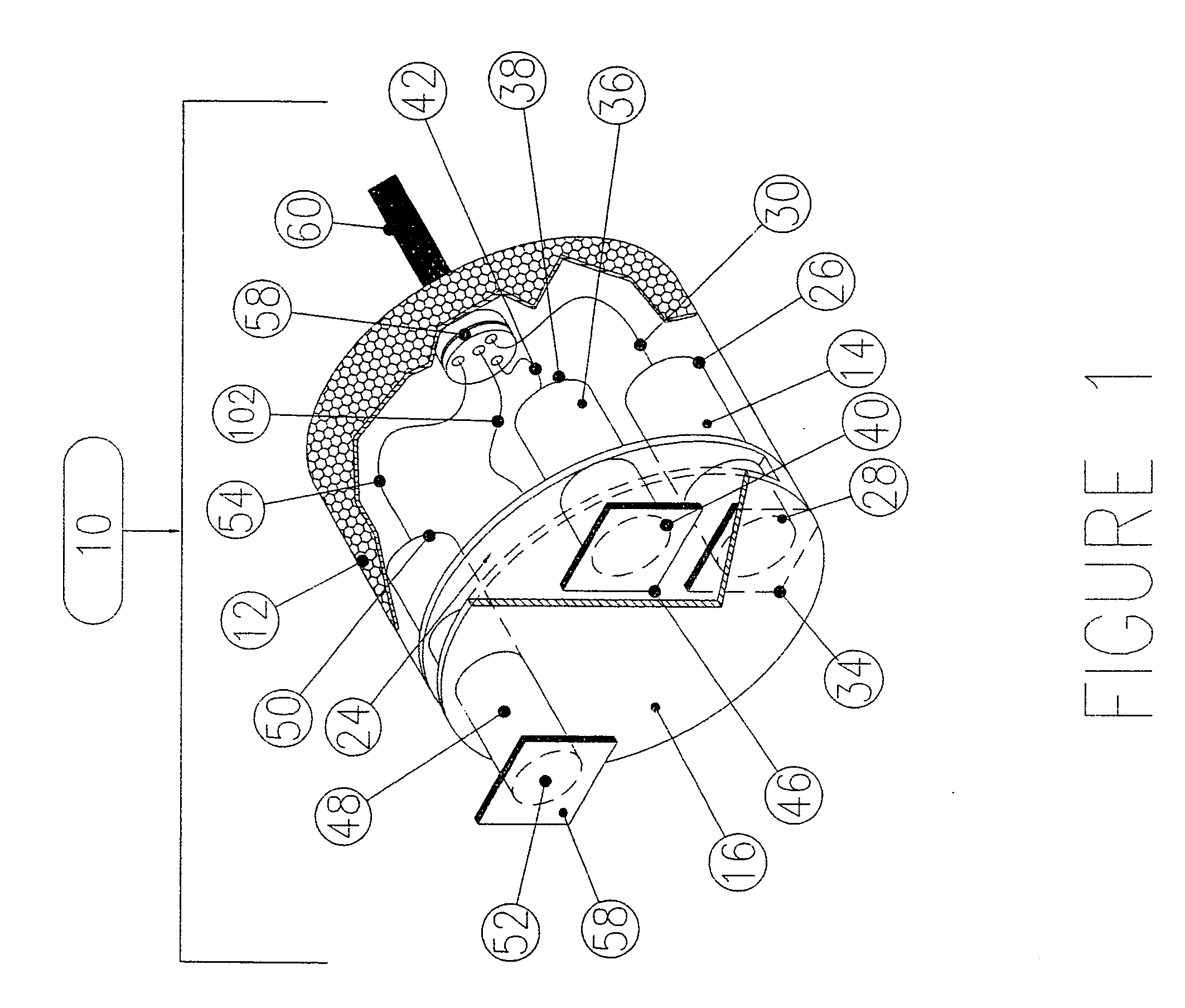
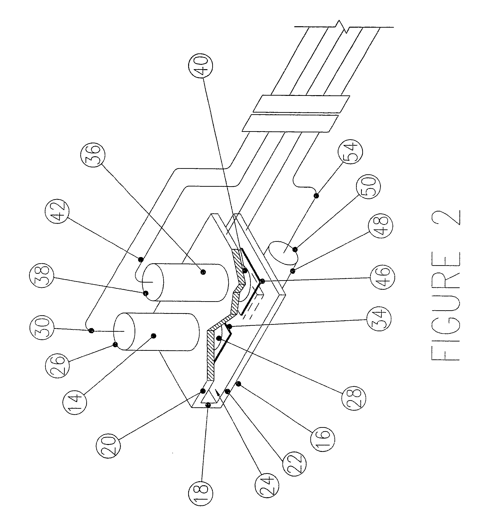
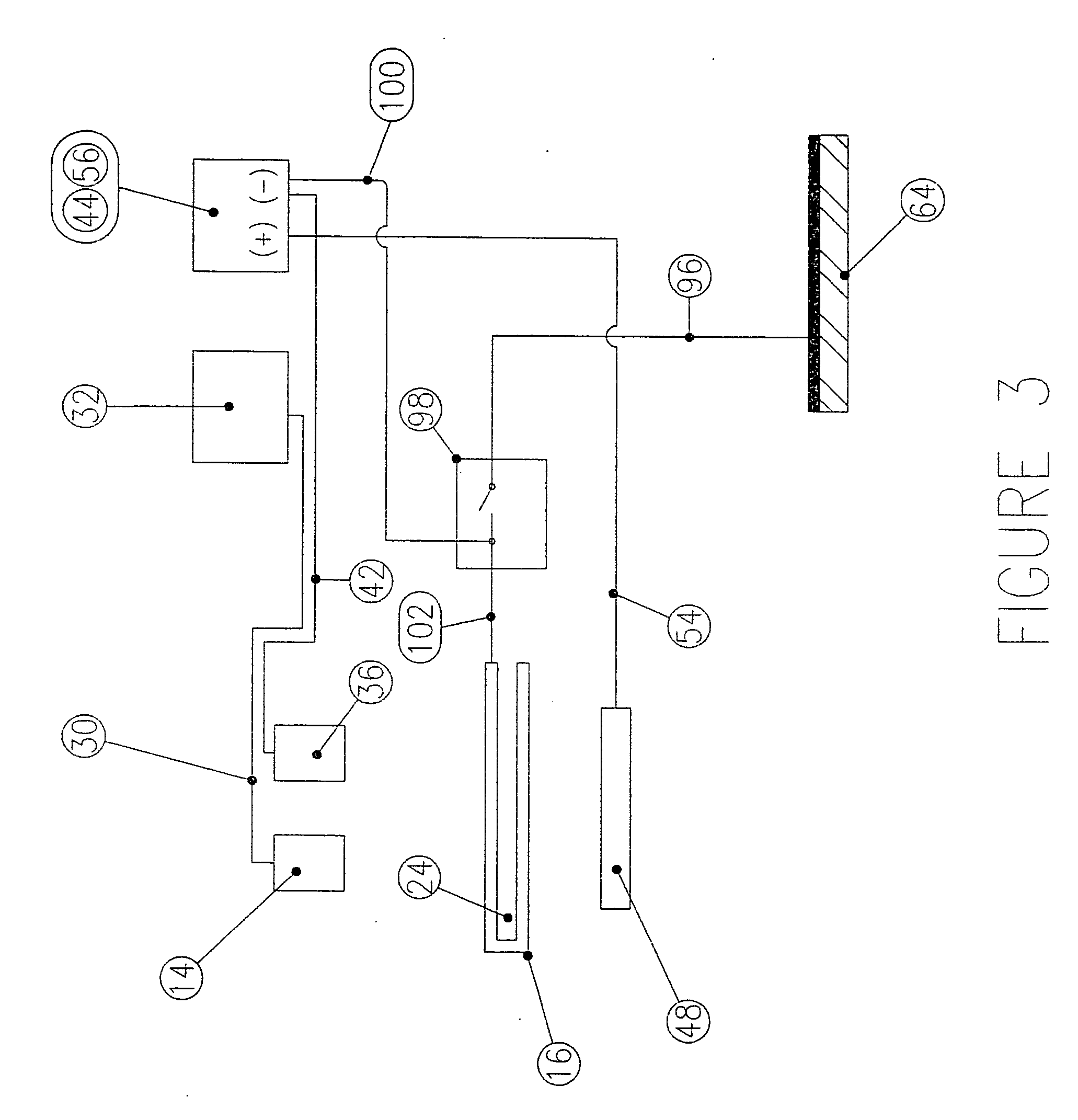
[0031] Referring to FIGS. 1 and 2, the present invention provides an apparatus 10 for measuring the efficacy of cathodic protection process at a surface of a metal structure 64 disposed in a location where visual inspection of the metal structure 64 is rendered difficult. The apparatus is useful for measuring and controlling the efficacy of cathodic protection at an internal surface of metal containments or, for example, at an underground or submerged metal structure 64, where such metal surfaces are exposed to an electrolytic environment.

[0032] The apparatus 10 includes a metal coupon 16 which is protected in a similar manner to the metal structure 64 in order to simulate the cathodic protection of the metal structure 64. A pH / temperature reference electrode 14, and potential sensing reference electrodes 36, 48 are provided to sense an indication of cathodic protection of the metal coupon 16, and, therefore, indirectly, within the protective film at the surface of the metal struct...


PUM

PropertyMeasurementUnit
voltage swingsaaaaaaaaaa
thickaaaaaaaaaa
temperatureaaaaaaaaaa

Abstract

The present invention provides a method and apparatus for instrumental analysis in remote locations. In one embodiment, the present invention provides a method of controlling cathodic protection being applied to a metal structure having a surface disposed in an electrolytic environment comprising electrically connecting a metal coupon to the surface of the metal structure, positioning the metal coupon at a predetermined position relative to the surface of the metal structure and within the electrolytic environment, applying a cathodic protection agent to the surface of the metal structure to effect cathodic protection of the surface of the metal structure, measuring a cathodic protection indication proximate to the metal coupon, comparing the cathodic protection indication with a predetermined value, and adjusting the cathodic protection agent being applied to the surface of the metal structure in response to the comparison. In this respect, the present invention provides a system for controlling the efficacy of cathodic protection being applied to a metal structure disposed in an electrolytic environment comprising an electrical vintage and current source of applying an electrical current to the metal structure to effect cathodic protection of the metal structure, a measurement apparatus for measuring the efficacy of the cathodic protection, the measurement apparatus being electrically connected to the metal structure, and a passage for receiving movement of the means for measuring to effect positioning of the measurement apparatus at a predetermined position relative to the metal structure. The passage of the present invention could also be used to facilitate non-destructive testing at remote locations, as well as to mitigate or prevent stray current discharge.

Description

FIELD OF THE INVENTION [0001] The present invention relates to a method and apparatus for measuring and controlling the efficacy of cathodic protection, and more particular it relates to a method and apparatus for measuring and controlling parameters and / or to improve the efficacy of cathodic protection at a metal surface disposed in a remote location where visual inspection of the metal structure is rendered difficult. BACKGROUND OF THE INVENTION [0002] Metal structures immersed in aqueous electrolytic environments are susceptible to corrosion. Corrosion occurs when the current discharges from the metal surface into the electrolyte, thereby creating anodic areas. Cathodic protection is applied to the metal structure with a view to forcing the entire structure surface exposed to the electrolyte to collect protective current. When this environmental condition has been attained, the structure's entire exposed surface becomes cathodic, and corrosion may be sufficiently mitigated, contr...

Claims


Application Information

Patent Timeline
Patent Type & Authority Applications(United States)
IPC IPC(8): C23F13/04G01N17/04
CPCG01N17/043C23F13/04C23F2213/11
Inventor RUSSELL, GORDON I.STENEKES, MURRAY D.
Owner G I RUSSELL
Why Eureka
Try Eureka